USB-C Explained: Why the Same Connector Delivers Different Charging Speeds and Data Rates
CC pins, e-marker chips, PD negotiation, and PCB signal integrity — the real engineering behind USB-C compatibility.
Table of Contents
USB-C charging speeds can differ enormously from port to port and cable to cable, even when the connector looks identical. Plug the same USB-C cable into two different laptops, and you can get two completely different results. One charges at full speed and drives an external monitor without complaint. The other trickle-charges, refuses to output video, and caps file transfers at speeds you’d expect from a decade-old flash drive. Same connector. Same cable, in some cases. Different outcome entirely.
This isn’t a legacy problem, either — it spans everything shipping today, from ordinary USB-C and baseline USB4 hardware to Thunderbolt 4, and now the newer 80Gbps USB4 Version 2.0 and Thunderbolt 5 tier just reaching the market.
That’s not a defect. It’s the predictable result of a decision USB-IF made when it designed USB-C: standardize the shape of the connector and the rules for negotiating over it, and leave almost everything else — which protocols get implemented, at what power level, over what distance — up to whoever builds the port, the cable, or the device. The connector became universal. The capability behind it never did.
What USB-C Actually Standardized
USB-C is a 24-pin, reversible connector spec with a defined pinout and a negotiation framework layered on top of it. That’s the entire mandatory core. USB4 speeds, high-power USB PD charging, DisplayPort output, Thunderbolt tunneling — every one of those sits in an optional tier that a manufacturer implements, partially implements, or skips outright, usually for cost reasons.
This is the root of almost every “USB-C is broken” complaint, and it’s also why the complaint is slightly misdirected. A port and a cable can meet the applicable USB Type-C mechanical and electrical requirements while supporting few of the optional higher-level capabilities users often associate with the connector. The connector guarantees the plug will physically fit and that basic negotiation will occur. It guarantees nothing about what gets negotiated.
CC Pins and Power Delivery Negotiation
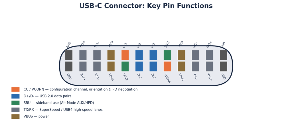
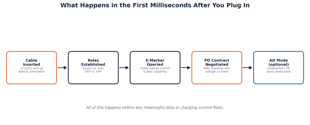
Two of the 24 pins in a USB-C connector — CC1 and CC2 — do most of the invisible work. Before any meaningful data or power flows, the source and sink use these Configuration Channel pins to establish cable orientation, power roles, and — when USB Power Delivery is supported — a power contract, negotiated currently under PD Revision 3.2 (Extended Power Range, enabling power levels up to 240W, was introduced back in Revision 3.1). Electronically marked cables can also participate in that CC-channel communication so the system can discover their capabilities and whether to enter an Alternate Mode at all.
This is USB Power Delivery. It’s not a fixed voltage pushed down a wire — it’s a negotiated contract, established and renegotiated dynamically over the CC channel via a signaling method called BMC (Biphase Mark Coding). A laptop might request more current under load and less at idle. A phone might request a different voltage than a tablet. None of that is visible to the user; it’s a digital handshake happening in the CC channel every time you plug in.
The practical consequence: if either end of that negotiation is incomplete — a cheap power bank with a stripped-down PD implementation, a port that only supports the minimum required PD profile — the connection quietly falls back to a lower, safer default. Nothing fails outright. If the source can’t offer a compatible higher-power PD contract, the device simply falls back to whatever lower Type-C current advertisement or legacy charging mode both ends actually support, and charges substantially more slowly — with the only symptom the user sees being “this is taking a while.” That same negotiated voltage/current contract has consequences beyond speed, too — it’s the reason raising voltage instead of current cuts resistive heating in the cable and connector, which I walk through stage by stage in Why Does Your Phone Get Hot While Charging?
E-Marker Chips and USB-C Charging Speeds
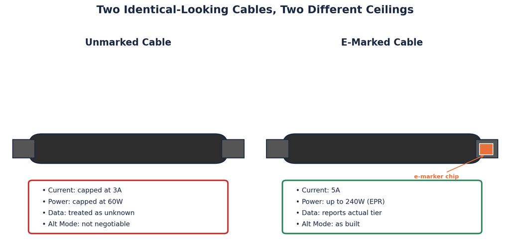
USB-C separates the cable’s current capability from the power level negotiated between source and sink. The default, unmarked tier tops out at 900mA for USB 3.0 signaling (500mA for USB 2.0) as basic bus power, while the Type-C current-advertisement scheme separately allows standard cables to advertise up to 3A at 5V without any embedded identification — and, under USB PD, that same 3A cable can still support negotiated contracts up to 60W at higher voltages. Push past 3A itself — into 5A territory, which unlocks 100W and, under PD 3.1’s Extended Power Range, up to 240W — and industry documentation consistently indicates the cable must carry an electronic marker chip embedded in the connector shell. This applies to what USB-IF itself calls an “electronically marked passive cable” — the high-speed signal path remains electrically passive; the e-marker is a small identification component layered on top of it, not a sign the cable has become “active” in the retimer sense. When the host queries the cable during negotiation, the e-marker reports back its actual certified capability: current rating, and for higher-speed cables, the data signaling tier and Alt Mode support it was built for.
A cable without an e-marker chip is treated as a basic, 3A-capped cable by default, regardless of how thick the copper inside actually is. This is a deliberate safety gate, not an oversight — it lets the system identify the cable’s capabilities, including current handling and, where applicable, high-speed characteristics, so the connection operates within supported limits rather than exceeding what the cable was validated for. But it also means two visually identical cables, one with an e-marker and one without, will negotiate to completely different power and data ceilings. There’s no way to tell which is which by looking at the outside.
This is where manufacturing cost pressure shows up directly. An e-marker chip is real silicon and real assembly cost inside what looks like a simple wire. Omitting it is a legitimate way to hit a lower price point — but it caps what that cable will ever do, permanently, regardless of what the rest of the cable could physically support.
USB 2.0 / 3.x / USB4 Signaling Differences
The USB-C connector has carried multiple generations of USB signaling since its introduction, and each generation has different requirements for how many differential pairs are used, how they’re routed, and what PHY — the physical layer transceiver silicon behind the connector — sits on both the host and device side.
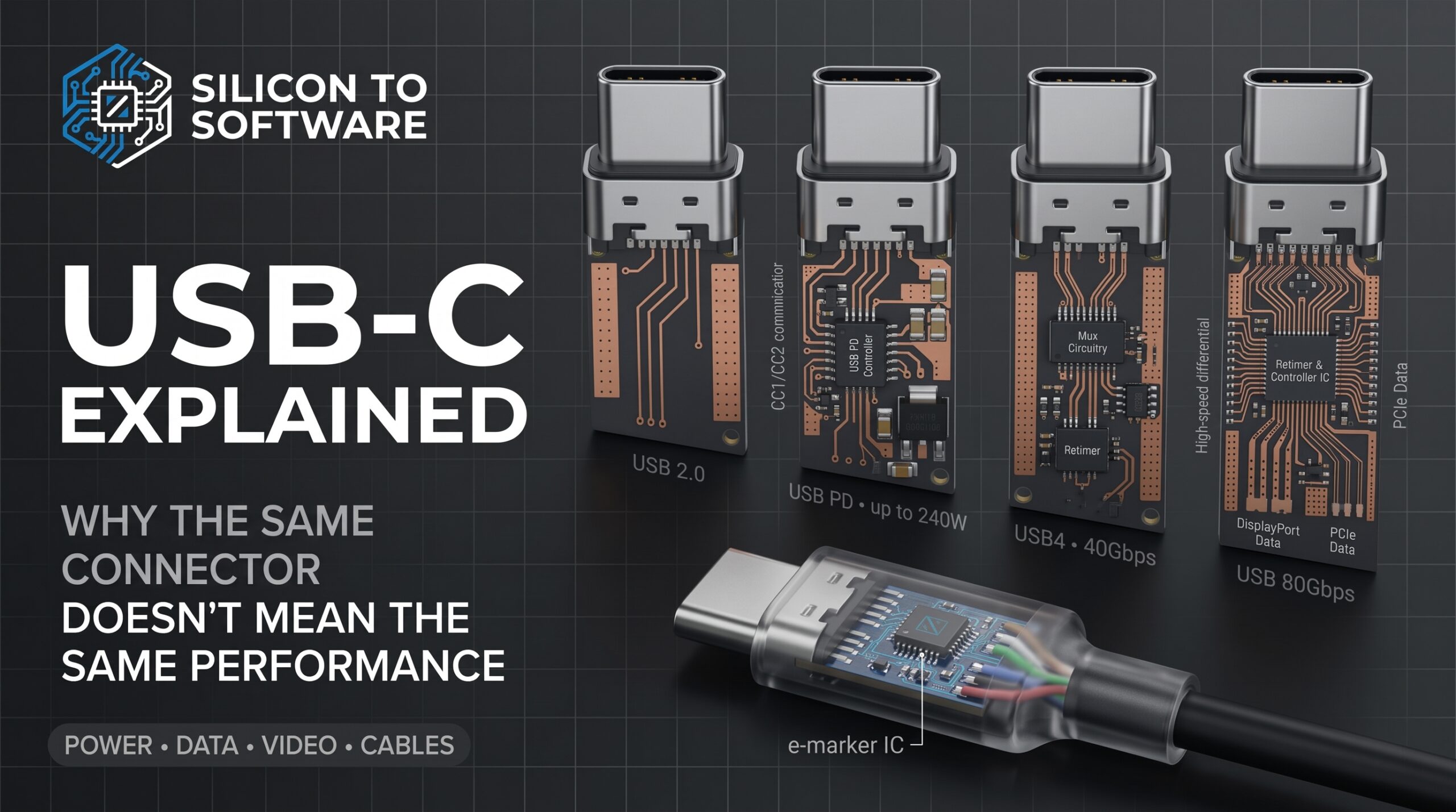
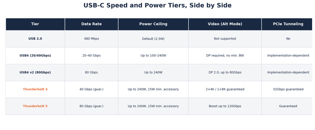
A device can implement a USB-C connector while only supporting USB 2.0 signaling underneath it — legal, compliant, and common on lower-cost accessories and cables where high-speed data was never the point. USB4 sits toward the other end, using a tunneling architecture that can carry USB 3.x traffic, DisplayPort, and PCIe over the same physical lanes depending on what’s been negotiated. The original USB4 specification tops out at 40Gbps using two Gen 3 lanes operating at up to 20Gbps per lane. That’s distinct from USB4 Gen 2 operation at 10Gbps per lane and from USB 3.2 Gen 2×2, which reaches 20Gbps aggregate using two 10Gbps lanes. USB4 Version 2.0, branded to consumers as “USB 80Gbps,” doubles the aggregate again to 80Gbps symmetric and up to 120Gbps in an asymmetric configuration favoring one direction. Reaching that higher tier over the same cable and board budget required a real change in physical-layer encoding — the 40Gbps tier uses conventional NRZ signaling, while the 80Gbps tier moves to PAM3, packing three voltage levels per symbol instead of two, which is what makes the doubled throughput possible without doubling the required channel bandwidth. USB 80Gbps support is now appearing in shipping host and peripheral implementations, including Thunderbolt 5 systems, which are built on the USB4 Version 2.0 foundation. Even within the more established 40Gbps tier, implementation is optional — a device can ship at 20Gbps or 40Gbps, and manufacturers routinely choose the lower tier to hold down cost.
That tiering shows up nowhere on the port itself, and that’s the actual engineering trade-off underneath it: backward compatibility means every generation has to coexist on the same physical interface, which means the interface alone can never tell you which generation is behind it. “USB-C” identifies the connector. It says nothing about whether you’re getting 80Gbps, 40Gbps, or base USB 2.0 — which is why data transfer speed is one of the most common sources of “this doesn’t work the way I expected” complaints.
DisplayPort and Thunderbolt Alt Modes
Video output over USB-C isn’t a separate physical connection riding alongside USB data — it’s a repurposing of the same high-speed lanes through what’s called an Alternate Mode. DisplayPort Alt Mode, developed jointly by VESA and USB-IF, can reallocate one, two, or all four of a connector’s high-speed differential pairs to DisplayPort signaling instead of USB data. The current version of the spec, DisplayPort Alt Mode 2.0, supports up to 80 Gbps of video bandwidth when all four lanes are dedicated to display traffic, or up to 40 Gbps of video alongside simultaneous SuperSpeed USB data. That 80Gbps figure is the raw link bandwidth; VESA’s own materials put DisplayPort 2.0’s actual usable payload, after 128b/132b channel-coding overhead, at up to 77.37Gbps across all four lanes — a real but secondary distinction worth knowing if you’re doing bandwidth math against a specific display’s requirements.
A USB-C connector by itself tells you nothing about video capability. USB4 changes that in principle — compliant USB4 hosts have DisplayPort Alt Mode support requirements on their downstream-facing ports, so a genuine USB4 host isn’t simply free to omit video entirely — but USB4 still doesn’t guarantee Thunderbolt-class display bandwidth or feature levels. Thunderbolt mandates those explicitly: Thunderbolt 4 host ports guarantee 40Gbps bidirectional bandwidth, 32Gbps of PCIe tunneling, support for two 4K displays (or one 8K display), and a minimum of 15W of accessory power, while a baseline USB4 port only guarantees 7.5W to accessories and does not impose Thunderbolt’s 32Gbps minimum PCIe data requirement — PCIe tunneling support there is implementation-dependent, and compliance testing for it only applies where a product actually claims the feature. Thunderbolt 5 extends the same guarantee logic to the higher tier: built on USB4 Version 2.0, it guarantees 80Gbps bidirectionally, with Bandwidth Boost able to provide up to 120Gbps in the transmit direction for display-intensive workloads.
This matters for a simple reason: a USB4-labeled port supports video in principle, but not necessarily at any particular resolution, refresh rate, or alongside full-bandwidth data — and a device can carry a fully compliant USB4 port that throttles a fast external SSD well below its rated speed if the implementation provides limited PCIe tunneling performance, or doesn’t support PCIe tunneling for that use case at all. A drive rated for 3,500 MB/s over PCIe gets no benefit from that rating if the port it’s plugged into caps real-world throughput at a fraction of what the drive can do.
Retimers, Muxes, and the PCB Reality Behind All of It
Here’s the part that doesn’t show up in any consumer explanation of USB-C, and it’s the part I actually deal with on the manufacturing side: none of the negotiation architecture above matters if the physical channel can’t hold signal integrity at the data rates being requested.
At the 40Gbps tier (USB4 Gen 3, using NRZ signaling at 20Gbps per lane), the transmitter and receiver terminals are commonly held to a nominal end-to-end insertion-loss budget of roughly 22.5dB at the 10GHz Nyquist frequency — a compliance-test guideline covering host PCB, cable, and device PCB combined, not a fixed physical law that applies identically across every topology. That budget is tight enough that full-speed passive cables at this tier are commonly limited to around 0.8 meters in practice, though the real constraint is the loss budget itself rather than a hard distance ceiling — a cable’s actual reach depends on conductor gauge, dielectric quality, and connector implementation as much as raw length. Push to the newer 80Gbps tier and the physical layer changes altogether: NRZ signaling can’t carry that much data within a comparable loss budget, so USB4 Version 2.0 moves to PAM3 encoding specifically to make the higher throughput possible over similar cable and board budgets.
Past those practical length ceilings, active cables — ones with retimer or redriver silicon built into the connector housing — regenerate the signal so it arrives usable at the far end. A retimer performs full clock-and-data recovery and retransmits a clean signal, at the cost of some added latency; a redriver is a simpler analog amplifier that reshapes the signal in real time without fully recovering it, trading some jitter performance for lower latency and cost.
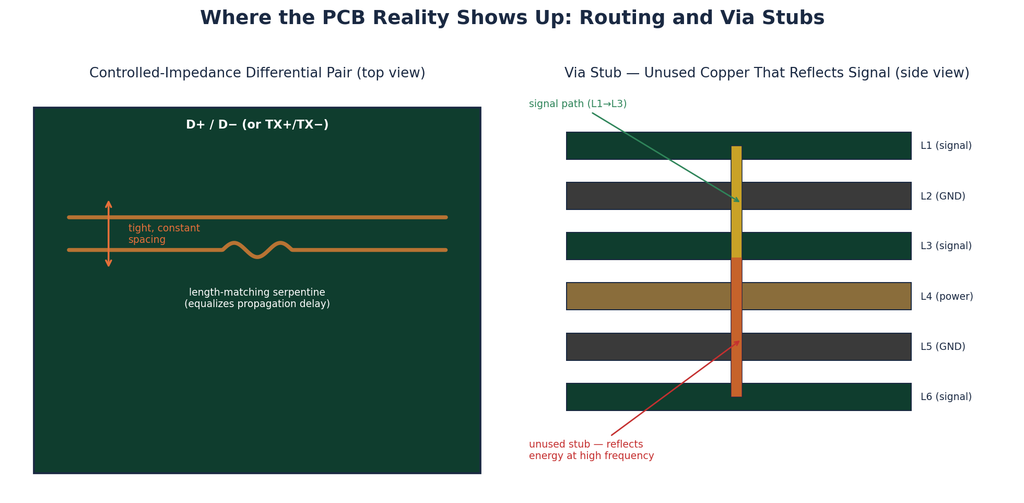
On the board side, this means controlled-impedance differential pair routing, tight length-matching tolerances between pairs, and careful management of via stubs that would otherwise reflect signal energy back into the channel at high frequencies. The laminate itself is part of that same channel budget — dielectric loss and copper roughness on the board eat into the same insertion-loss margin discussed above, just further up the signal chain than the cable or connector. I go deeper on how that material-side tradeoff actually gets decided in Choosing the Right High-Speed Laminate for AI Hardware, which covers the same discipline applied to board material selection rather than connector design.
Muxes solve a different problem than retimers do. Since a single set of high-speed differential pairs might carry USB data in one negotiated state and DisplayPort or Thunderbolt traffic in another, a mux is the analog switch that physically routes those pairs to the correct destination silicon based on what got negotiated over the CC channel — it’s a routing decision, not a signal-quality one, though a poorly laid-out mux path introduces its own discontinuity that a retimer downstream then has to compensate for.
This isn’t cutting corners in the pejorative sense. It’s a direct cost-versus-performance tradeoff: retimers, precision board layout, and mux silicon all cost money and board space. A manufacturer building a budget device or accessory has a real incentive to implement less of this — and the result is a port that still says “USB-C” on the outside while delivering a fraction of what a fully built-out implementation would.
The Part Nobody’s Fixed
The engineering here is well designed — the negotiation layer arbitrates power delivery, data signaling, and protocol selection over a single physical interface without ever needing the user to configure anything manually.
What hasn’t kept pace, at least through voluntary means, is disclosure. USB-IF has actually strengthened its labeling requirements over time — cables entering its compliance program now carry mandatory 60W or 240W power markings, along with data-rate markings for most certified USB-C cables. It’s a real, documented, and increasingly rigorous system, not vaporware. The gap is that participating in USB-IF certification itself isn’t universally required for every cable sold in commerce. A cable or accessory maker can ship a fully USB-C-compliant product without ever going through that certification process, which means the logo and its markings tell you something when they’re present, and tell you nothing when they’re absent. In cost-sensitive sourcing, I routinely encounter cables shipped without those markings — a professional observation from where I sit in manufacturing, not a market-share estimate.
The EU addressed part of the same consumer-information problem through regulation rather than voluntary certification. The EU’s Common Charger Directive already mandates USB-C as the wired charging port on phones and small electronics, and extends that requirement to laptops placed on the EU market from April 28, 2026 onward — with mandatory USB Power Delivery support for devices requiring more than 15W, a packaging pictogram indicating whether a charger is included, and separate consumer information specifying the device’s charging requirements. This makes disclosure mandatory for at least one dimension of charging capability — power. Data rate, video support, and Alt Mode capability remain outside that mandate, which means the disclosure problem is only partially solved, and only in one regulatory jurisdiction.
That’s the unresolved problem. Not the engineering — the fact that knowing what a given port or cable can actually do still depends on optional certification, mandatory regulation that only covers part of the picture, or reading a spec sheet most consumers will never see.
About the Author
Imran Valiani | Sales Director, PCB Electronics Manufacturing
20+ years working with major Bay Area and global tech clients. Founder of Silicon to Software, where I write about the hardware layer — PCB fab, AI gear, autonomous systems, and cyber — the stuff most tech writers have never touched. Literally.
Follow: X @SiToSoftware | LinkedIn
This article was developed with AI assistance and edited, fact-checked, and reviewed by the author. See my full AI disclosure.
Sources
- USB Implementers Forum — “USB Type-C® Cable and Connector Specification, Release 2.5” USB-IF https://usb.org/document-library/usb-type-cr-cable-and-connector-specification-release-25
- USB Implementers Forum — “USB Power Delivery Specification, Revision 3.2, Version 1.2” USB-IF https://www.usb.org/document-library/usb-power-delivery
- USB Implementers Forum — “USB 80Gbps Announcement” USB-IF, October 2022 https://www.usb.org/sites/default/files/2022-10/USB-IF%20USB%2080Gbps%20Announcement_FINAL_v2.pdf
- VESA — “VESA Brings DisplayPort to New USB Type-C Connector” Video Electronics Standards Association, September 2014 https://vesa.org/featured-articles/vesa-brings-displayport-to-new-usb-type-c-connector/
- VESA — “VESA Releases Updated DisplayPort Alt Mode Spec to Bring DisplayPort 2.0 Performance to USB4 and New USB Type-C Devices” Video Electronics Standards Association, April 2020 https://vesa.org/featured-articles/vesa-releases-updated-displayport-alt-mode-spec-to-bring-displayport-2-0-performance-to-usb4-and-new-usb-type-c-devices/
- Intel — “Thunderbolt Technology: A Universe of Possibilities” Intel https://www.intel.com/content/www/us/en/architecture-and-technology/thunderbolt/overview.html
- Intel — “Intel Introduces Thunderbolt 5 Connectivity Standard” Intel Newsroom https://newsroom.intel.com/client-computing/intel-introduces-thunderbolt-5-standard
- Keysight Technologies — “USB 80Gbps: What’s New in USB4 Version 2?” Keysight https://www.keysight.com/blogs/en/tech/bench/2022/11/08/usb-80gbps-whats-new-in-usb4-version-2
- GraniteRiverLabs — “Welcome to the 80Gbps Ultra-High Speed Era of USB4” GraniteRiverLabs https://www.graniteriverlabs.com/en-us/technical-blog/usb4-80-cio80
- European Union — “Directive (EU) 2022/2380 and related Common Charger guidance” EUR-Lex, Official Journal of the European Union https://eur-lex.europa.eu/legal-content/EN/ALL/?uri=CELEX%3A52024XC02997
- European Commission — “The EU Common Charger” Single Market for Green and Digital Transition, European Commission https://single-market-economy.ec.europa.eu/sectors/electrical-and-electronic-engineering-industries-eei/radio-equipment-directive-red/one-common-charging-solution-all_en
- Diodes Incorporated — “Use a ReDriver or ReTimer for Longer and Thinner USB, USB Type-C, and DP Cables” Diodes Incorporated https://www.diodes.com/design/support/technical-articles/use-a-redriver-or-retimer-for-longer-and-thinner-usb-usb-type-c-and-dp-cables
- USB Implementers Forum — “USB Type-C Cable Logo Usage Guidelines” USB-IF, September 2024 https://www.usb.org/sites/default/files/usb_type-c_cable_logo_usage_guidelines_20240903.pdf