Choosing the Right High-Speed Laminate for AI Hardware: Megtron 6 vs. Megtron 8 vs. Tachyon 100G
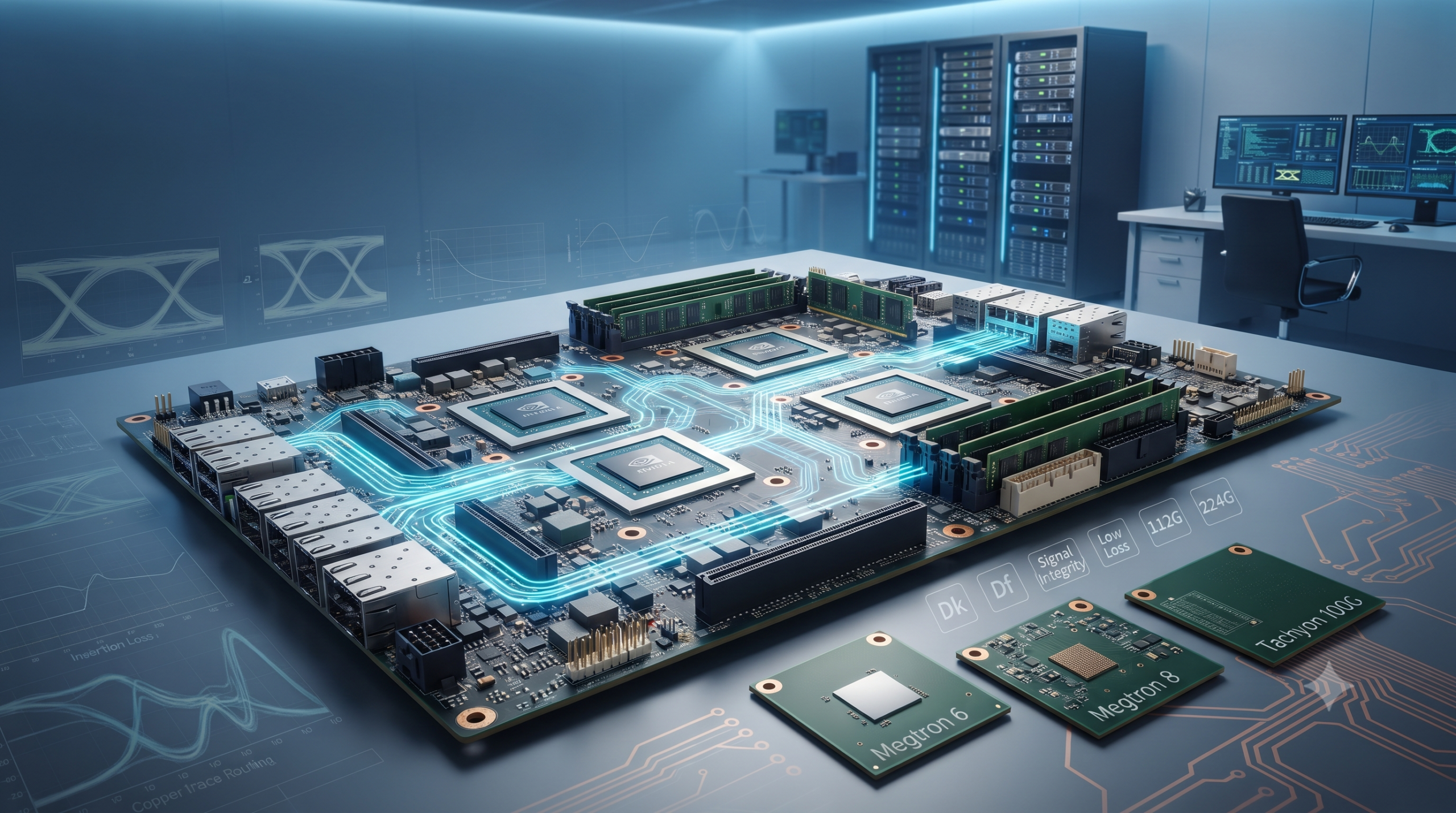
As AI servers, GPUs, and 112G/224G networking push PCB signal integrity to its limits, selecting the right high-speed laminate for AI hardware is no longer optional. Here’s how Megtron 6, Megtron 8, and Tachyon 100G compare in dielectric loss, manufacturability, cost, and real-world AI hardware performance.
Table of Contents
The board comes back wrong
Picking the right high-speed laminate for AI hardware sounds simple until a board comes back from first-article inspection with insertion loss numbers that don’t match simulation.
Nothing wrong with the layout. Stackup checks out. Fab process ran clean.
The laminate spec sheet just didn’t tell the whole story.
Here’s the thing. Every signal integrity engineer hits this moment eventually — a 112G SerDes channel won’t close its eye diagram, and you trace it back to one decision made months earlier. Buried in a materials selection meeting. Which laminate got specced for the job?
Why laminate choice matters more now
Laminate selection used to be a minor line item. Not anymore.
At 112G and 224G per lane, dielectric loss stops being a footnote. It becomes one of the two dominant terms in your channel budget, alongside conductor/copper-roughness loss — copper roughness, Dk stability across frequency, Df at your actual operating frequency, all compounding over an 8 to 12 inch backplane trace. Roughly speaking, 112G PAM4 works out to about 28 GHz Nyquist, and 224G PAM4 to about 56 GHz Nyquist — that’s roughly the Nyquist point your channel analysis needs to account for, not the 1 GHz figure most datasheets lead with. This isn’t a problem unique to AI hardware, either — the same material physics shows up wherever data rates climb, including the terahertz-class demands 6G infrastructure is starting to run into.
I’ve found that most beginners assume “high-speed laminate for AI hardware” means one category of material. It doesn’t. There’s a real spread in performance, cost, and manufacturability between the three names you’ll hear most in AI hardware conversations: Megtron 6, Megtron 8, and Tachyon 100G.
One thing worth flagging before we go further (and this trips people up more than it should): all three materials ship in multiple copper foil roughness grades — standard, VLP, H-VLP/HVLP2/HVLP3 depending on who’s naming it. Foil choice changes measured insertion loss independent of the resin system. Sometimes by more than the Dk/Df gap between two competing laminates. Comparing loss numbers across vendors or datasheets? Confirm you’re looking at the same copper grade first. Otherwise, the comparison isn’t telling you what you think it’s telling you.
Let’s get into what actually separates these three resin systems.
Megtron 6: the safe, proven baseline for high-speed laminate in AI hardware
Megtron 6’s been around for over a decade. Most fabs already know how to run it.
Per Panasonic’s official R-5775/R-5670 PDF datasheet:
- Dielectric constant (Dk): 3.71 @ 1 GHz / 3.61 @ 10 GHz for the standard R-5775 grade. This isn’t the only number you’ll see quoted for Megtron 6 — Panasonic’s own construction tables show Dk ranging from roughly 3.19 to 4.07 depending on glass style (1035, 1078, 2116, 3313, etc.) and resin content. These aren’t competing claims; they’re different buildable constructions within the same product family. Confirm which specific construction your fab is quoting before locking in impedance targets.
- Dissipation factor (Df): 0.002 at 1–2 GHz, per Panasonic’s own frequency-swept datasheet data. That number climbs as frequency increases — 0.003 at 4–6 GHz and 0.004 at 8–10 GHz on the same datasheet, consistently across every construction listed. If your channel’s actual operating frequency is in the 8 GHz+ range, quote the 0.004 figure in your budget, not the 0.002 headline number every marketing page leads with.
- Glass transition temp (Tg): 185°C by DSC / 210°C by DMA — Panasonic’s datasheet reports both. Worth flagging: when you see Megtron 6, Megtron 8, and Tachyon 100G specs compared side by side (including in the table further down this page), check which test method each figure uses before treating “Tg” as one apples-to-apples column. Megtron 8’s 220°C figure is a DMA measurement; comparing it directly against Megtron 6’s DSC figure of 185°C makes the gap look bigger than it is on a like-for-like basis (210°C DMA vs. 220°C DMA is a much smaller difference).
- Thermal decomposition temp (Td): 410°C
Why does it still show up in new AI server designs? A few reasons.
In general industry practice, Megtron 6 processes similarly to standard FR-4 — typically no plasma desmear step, no exotic pretreatment for through-hole copper plating. Sampling cycles stay short as a result. That matters a lot when you’re iterating on a GPU baseboard under a tight schedule.
- Best for: 25G–56G interconnect, established fab relationships, cost-sensitive multilayer builds
- Watch out for: it starts to run out of headroom once you’re pushing 112G+ over longer trace lengths
To be honest, if your design margin is generous and your traces are short, Megtron 6 is still a completely reasonable call. Don’t over-spec just because a newer material exists.
Megtron 8: built for the next jump
Megtron 8 is Panasonic’s answer to where AI networking is actually headed.
Confirmed against Panasonic’s own Megtron 8 product page:
- Dk: 3.08 @ 14 GHz / Df: 0.0012 @ 14 GHz — this is the R-579Y(U) grade specifically. There’s a second SKU, R-579Y(N), that comes in at Dk 3.13 / Df 0.0016 @ 14 GHz — noticeably worse Df. Same Tg and Td for both. Specify the exact grade you qualified in your BOM and fab documentation — don’t assume (U) and (N) are interchangeable just because they share a family name.
- Tg: 220°C (DMA)
- Td: 370°C
The Df number is the headline. Panasonic states roughly a 30% improvement in transmission loss compared to Megtron 7, measured at 28 GHz — that’s a vendor-stated comparison, not an independent benchmark. Worth validating against your own channel simulation. But it’s Panasonic’s own factory documentation, not a secondhand distributor summary, so I’d take it more seriously than most vendor claims.
Worth knowing about before you commit to a program: Panasonic has also publicly positioned Megtron 9 for 224 Gbps designs — showcased at DesignCon back in January 2025. I couldn’t find a more recent public update. No public Dk/Df specs either. I’m not asserting an availability or shipping status one way or the other here (that’s not my call to make from a trade-show photo). If you’re speccing a platform with a multi-year lifespan, just ask your Panasonic contact where that program actually stands.
Why might that matter for AI hardware specifically? Because 800GbE-class switch silicon and next-gen GPU interconnects are exactly where Megtron 6’s loss budget gets difficult to close over longer channels.
A few practical notes:
- Higher reported Tg (220°C vs. Megtron 6’s 185°C) suggests more thermal headroom for dense multilayer stackups with heavy thermal cycling — worth confirming against your own reliability testing. That reliability testing question is worth taking seriously on its own: I go deep on the actual CTE-mismatch mechanism behind solder joint thermal fatigue, and why Tg alone isn’t the whole story, in Industrial IoT Hardware Reliability.
- Lower reported Td (370°C vs. Megtron 6’s 410°C) implies somewhat less margin during rework; this is an inference from the Td delta, not a sourced claim about measured rework yield
- Fab familiarity is likely lower than Megtron 6, given its shorter time on the market — this is an inference from relative market tenure, not a measured industry statistic, so expect a longer qualification runway on a new program regardless
Best for: 112G+ SerDes, next-gen switch fabrics, designs where you’re deliberately building in margin for a platform refresh
The tradeoff is cost and availability. Megtron 8 isn’t stocked as broadly. Not every fab has a proven process window dialed in yet. Ask early. Don’t find out six weeks before tape-out.
Tachyon 100G: the low-Dk alternative
Isola’s Tachyon 100G isn’t actually new. Been in production since 2014. Better described as the established third option than an upstart — but it took a genuinely different design philosophy from the Megatron line. Instead of chasing the lowest possible Df, it went for PTFE-adjacent electrical performance on a resin system you can actually process on standard FR-4 equipment.
Per Isola’s current Tachyon 100G laminate/prepreg datasheet (Revision H, 2026):
- Dk: 3.02 (nominal), stable from -55°C to +125°C
- Df: 0.0021 (nominal, main properties datasheet). The separate construction-specific Dk/Df table shows more spread than this single number suggests — across actual laminate and prepreg constructions (different glass styles and resin contents), Df runs from about 0.0013 up to 0.0022 depending on what you’re building. Pull the exact construction row for your glass style before using a single “0.0021” figure in a real channel budget.
- Tg: 215°C (DSC) / 230°C (DMA) / 210°C (TMA)
- Td: 360°C (TGA @ 5% weight loss)
Worth noting: these thermal figures run higher than older Tachyon 100G literature suggests. Earlier datasheet revisions listed a lower Tg. Isola’s updated the material’s characterization data over time — so if you’re pulling numbers from an old PDF sitting in a shared drive somewhere (we’ve all got one of those folders), re-download the current revision instead of trusting a cached copy.
Isola’s current Rev H datasheet, last updated June 23, 2026, states these properties are stable “between -55°C and +125°C up to 100 GHz.” That’s the figure to use going forward. An older revision I’d pulled cited a lower 40 GHz figure, which appears superseded. Working from a cached PDF? Re-pull the current Rev H version. Note too that the separate construction-specific Dk/Df table — a distinct document, currently at Revision M — is where you’ll find values for your exact glass style and resin content. The 100 GHz stability claim lives on the main properties sheet, not necessarily every individual construction line item.
Worth being precise about what that 100 GHz figure actually covers: it’s a general material-stability statement from Isola’s main properties sheet, not a per-construction measured dataset. The construction-specific Dk/Df table — the one with actual numbers for your exact glass style and resin content — only publishes measured data up to 20 GHz. For 224G PAM4 work, where your real operating frequency lands around 56 GHz Nyquist (see the earlier note on this), that’s a meaningful gap between the general stability claim and what’s actually been measured per construction. The 100 GHz statement does not establish construction-specific signal integrity performance at 56 GHz — it’s a broader material claim, not a substitute for measured data at your actual operating frequency. Don’t treat the 20 GHz construction table as validated 56 GHz data, and don’t extrapolate it yourself without checking with Isola directly for your specific build.
Notice something on the Dk/Df numbers? Tachyon 100G’s nominal Dk is lower than the headline Megtron 6 and Megtron 8 values shown here. Its Df sits in the middle — better than Megtron 6, not quite matching Megtron 8.
Where Tachyon 100G earns its keep is the combination of low Dk and standard processing. No plasma treatment for through-hole prep. Compatible with existing FR-4 lamination and drilling workflows. That lower Dk also shortens propagation delay and can ease trace-width tuning for controlled impedance. A real design convenience. Not just a marketing bullet.
One process note that’s easy to miss, though: Tachyon 100G ships with moisture-barrier-bag packaging requirements. Per Isola’s datasheet, once the bag is opened, boards need processing within 168 hours at shop floor conditions of ≤30°C/60% RH, with a humidity indicator card and desiccant in the bag. FR-4-compatible in terms of lamination and drilling, sure. Doesn’t mean zero extra handling. Plan your fab’s floor-life window accordingly — it’s the same category of tradeoff we’ve run into writing about PCB material selection for satellite electronics, just a very different environment driving the constraint.
Best for: teams wanting PTFE-adjacent loss numbers without a PTFE-level manufacturing headache, mixed digital/RF backplane designs
One honest caveat: Tachyon 100G isn’t the best on every axis in Isola’s own current lineup. Per Isola’s own product comparison page, TerraGreen 400G does beat Tachyon 100G’s Df (0.0017 vs. 0.0021) — that’s Isola’s own first-party figure, not a third-party claim.
Tachyon 100G’s advantage, once you compare like for like, is thermal margin: 215°C Tg vs. TerraGreen 400G’s 200°C, and 215°C DSC (230°C DMA) vs. Megtron 6’s 185°C DSC (210°C DMA). Tachyon even edges out Megatron 8’s 220°C DMA figure on a same-method comparison. That matters more than raw Df on high-layer-count line cards with heavy thermal cycling.
TerraGreen 400G’s tradeoff going the other way? It’s halogen-free — a real requirement on some OEM specs — while Tachyon 100G isn’t. If halogen-free compliance isn’t a project requirement for you, it’s one less constraint to design around.
Side-by-side, at a glance
[Suggested image placement: a rendered version of the comparison table below as a chart or graphic — this satisfies both the “rich media” and “image alt text” checks. Suggested alt text: “high-speed laminate for AI hardware comparison chart — Megtron 6 vs Megtron 8 vs Tachyon 100G Dk and Df values.”]
| Laminate | Dk | Df @ 1–2 GHz | Df @ 10 GHz | Tg (DSC) | Tg (DMA) | Best fit |
|---|---|---|---|---|---|---|
| Megtron 6 | 3.71 (standard grade @1GHz); 3.19–4.07 across constructions | 0.0020 | 0.0040 | 185°C | 210°C | 25G–56G, cost-sensitive |
| Megtron 8 (R-579Y(U)) | 3.08 (@14GHz) | — | 0.0012 (@14GHz) | — (not published) | 220°C | 112G+, next-gen switch fabrics |
| Tachyon 100G | 3.02 | 0.0021 (nominal) | — | 215°C | 230°C | Low-Dk-priority, mixed digital/RF |
All figures checked directly against each vendor’s current public documentation: Panasonic’s R-5775(N)/(K)/(G) PDF datasheet for Megtron 6, Panasonic’s Megtron 8 product page, and Isola’s Tachyon 100G Revision H datasheet. Tachyon’s 0.0021 figure is the nominal value from Isola’s main properties datasheet, not a separately measured value at each listed frequency — the construction-specific Dk/Df table is a distinct dataset with its own frequency and test-method context, covered earlier in this piece.
Note the Tg columns are split by test method deliberately. Panasonic doesn’t publish a DSC figure for Megtron 8, so comparing “Tg” as a single number across all three materials mixes test methods and can mislead. On the DMA basis, where all three have a published figure, the actual order is Tachyon 100G (230°C) > Megtron 8 (220°C) > Megtron 6 (210°C). The Df columns carry a similar caveat: the frequency conditions differ by row (Megtron 6 at 1–2 GHz and 10 GHz, Megtron 8 at 14 GHz, Tachyon at its nominal ~1 GHz figure), so don’t read these Df values as directly comparable without also checking the measurement frequency behind each one.
Construction-specific values (glass style, resin content, copper foil) will vary from these headline numbers — pull the exact construction table for your build rather than treating this row as a spec you can cite directly.
Worth knowing: Rogers’ RO1200 (ceramic-filled, Dk 3.05, Df 0.0017 @ 10 GHz) is a fourth option in this same class that this piece doesn’t cover in depth. Panasonic has also publicly positioned Megtron 9 for 224G designs, though public specs weren’t available as of this writing.
What actually decides it
Don’t pick a laminate off a spec sheet alone. Ask three questions first.
What’s your target data rate, really? Not the marketing number — the actual per-lane rate on your longest channel. What’s your fab’s proven process window, copper foil grade included? And what’s your cost ceiling per panel at your actual layer count?
A 224G design with long backplane traces is a poor fit for Megtron 6’s loss budget. That’s an engineering heuristic based on the Df numbers above, not a rule pulled from a spec sheet, so validate it against your own channel simulation. A 56G daughter card with a short trace run, on the other hand, often doesn’t justify Megtron 8’s additional material cost.
The quiet argument nobody puts on a slide
There’s a quiet argument happening inside every AI hardware team right now. It rarely makes it into the marketing slides: which laminate actually earns its premium?
Megtron 6’s been the safe, proven choice for a decade. Megtron 8 promises headroom for the next generation of interconnect speeds. Tachyon 100G has been the low-Dk alternative in production since 2014, and it’s still competitive on its own terms rather than being the new kid on the block.
On paper, this looks like a simple upgrade path.
That same discipline — match the material to what the application actually needs, not to what’s newest on the spec sheet — shows up anywhere a manufacturing process gets chosen under competing constraints. I ran into the same tension writing about printed conductive ink versus flexible PCB manufacturing recently: the tradeoff there is between conductivity, flexibility, and process temperature, but the underlying discipline is identical.
In practice? It’s a set of trade-offs between dielectric loss, manufacturability, and cost that can quietly make or break a 224G design. The engineer who gets this right isn’t the one who picked the lowest Df on the datasheet. It’s the one who matched the material — and the exact construction, copper grade, and moisture handling requirements that come with it — to the actual channel, the actual fab, and the actual budget. Before the first article inspection. Not after.
About the Author
Imran Valiani | Sales Director, PCB Electronics Manufacturing
20+ years working with major Bay Area and global tech clients. Founder of Silicon to Software, where I write about the hardware layer — PCB fab, AI gear, autonomous systems, and cyber — the stuff most tech writers have never touched. Literally.
Follow: X @SiToSoftware | LinkedIn
For more analysis of signal integrity, materials, interconnects, and board-level design constraints, explore the PCB Design & Signal Integrity Resource Hub.
This article was developed with AI assistance and edited, fact-checked, and reviewed by the author. See my full AI disclosure.
Key sources referenced:
- Panasonic Industrial Devices — Megtron 6 (R-5775/R-5670) official PDF datasheet
- Panasonic Industrial Devices — Megtron 7 (R-5785/R-5680) official PDF datasheet, No. 19071228
- Panasonic Industrial Devices — Megtron 8 (R-5795/R-579Y) product page and PDF datasheet, No. 240724
- Panasonic Industrial Devices — Megtron 9 announcement (DesignCon)
- Isola Group — Tachyon 100G Ultra Low Loss Laminate and Prepreg datasheet, Revision H, June 23, 2026
- Isola Group — Tachyon 100G construction-specific Dk/Df table, Revision M (separate document)
- Rogers Corporation — XtremeSpeed RO1200 laminate datasheet
- Isola Group — own product comparison page listing TerraGreen 400G and Tachyon 100G side by side
- Matrix USA — distributor circuit-board-material comparison table (superseded for Megtron 7 by the primary datasheet above; no longer relied on for that figure)