How AI Is Transforming Modern Cars: Autonomous Driving, EV Technology, and the PCB Engineering Powering It All
From Tesla Full Self-Driving chips to Waymo’s advanced sensor stack, today’s vehicles are becoming AI-powered computers on wheels — driven by high-performance PCB engineering, automotive electronics, and next-generation autonomous systems.
Table of Contents
Nobody warned me the car was running a supercomputer. My colleague merged onto the freeway, dropped his hands into his lap, and kept talking. The vehicle tracked the lane on its own. Held a banked curve at highway speed. Modulated through a construction merge without a single human input. From the passenger seat, it looked almost boring — and that’s exactly the point.
Here’s what I’ve found after years on the supply side of this industry: the story most coverage gets wrong isn’t about the AI. It’s about the hardware beneath the AI — and specifically, about automotive PCB design. The custom system-on-chips running at the edge of what a 7nm process node can physically do inside a moving vehicle.
The printed circuit boards populated with AEC-Q100-qualified semiconductors and fabricated to IPC-6012DA automotive performance requirements — boards that have to survive thermal excursions and mechanical vibration profiles that would disable a standard laptop within weeks (though to be precise, ruggedized industrial and military-grade electronics are engineered for comparable environments; what separates automotive is the combination of AEC-Q100 qualification timelines, a 15-year field life mandate, and zero tolerance for safety-critical failures).
The battery management systems making real-time decisions across hundreds of lithium-ion cells at 400 to 800 volts. That stack — not the demo video, not the press release — is where the actual engineering story lives.
From Simple ECUs to Distributed Compute Platforms
Wind back thirty years. The most sophisticated electronic system in a passenger vehicle was probably the engine control unit — a single microcontroller handling fuel injection and ignition timing. That’s it. Today, a premium vehicle deploys between 100 and 150 discrete ECUs, per Wikipedia’s Electronic Control Unit article corroborated by Precedence Research’s automotive ECU market analysis. A standard sedan runs 15 to 20. Your 1990s Civic had maybe 3. Each is its own embedded controller on its own PCB, handling a specific domain: powertrain management, advanced driver assistance, body control, thermal regulation, infotainment, chassis dynamics, lighting.
The car became a distributed compute platform. Not metaphorically — literally. Multiple processor architectures. Multiple operating systems. Multiple communication buses running in parallel — CAN and LIN for legacy control functions, automotive Ethernet (100BASE-T1 and 1000BASE-T1, per IEEE 802.3bw/bp) increasingly dominant for high-bandwidth domains. It’s worth noting that next-generation zonal E/E architectures — being deployed now by Tesla, BMW (Neue Klasse), Rivian, and Volkswagen (SSP platform) — are actively reducing discrete ECU counts toward 10 to 30 domain and zonal controllers. The 100–150 ECU figure reflects today’s production vehicles on legacy architectures; the industry is heading toward consolidation.
FlexRay (standardized as ISO 17458) remains active in safety-critical deterministic applications — chassis control, X-by-wire systems, high-voltage battery coordination — in premium platforms from BMW, Audi, and Mercedes-Benz, where Ethernet’s non-deterministic latency characteristics remain a concern for hard real-time control loops. The trend is a hybrid network architecture: Ethernet for high-bandwidth domains, FlexRay where determinism is non-negotiable, CAN/LIN for body and powertrain.
The mechanical engineering story that defined the automobile for a century hasn’t gone away. It’s just been joined — and in some respects overtaken — by an embedded systems engineering story built on automotive PCB design that most consumers never see.
Two macro forces drove this. AI inference hardware matured to the point where real deep learning workloads could run at the edge, inside a vehicle, in real time, within an automotive power budget. And the EV transition rewrote the vehicle’s electrical architecture from the ground up — replacing the 12V domain assumptions that governed automotive electronics for decades with 400V to 800V traction systems that demand a completely different approach to PCB design, isolation coordination, and EMC management. Together: the modern software-defined vehicle. Separately, neither would have been sufficient.
The AI Hardware Architecture Driving Autonomy
Vision-Only vs. Redundant Multi-Modal Sensor Stacks
The central hardware debate in autonomous vehicle development isn’t about algorithms. It’s about sensors. Specifically, is a vision-only architecture sufficient, or does safe autonomy require a redundant multi-modal stack combining cameras, millimeter-wave radar, and lidar?
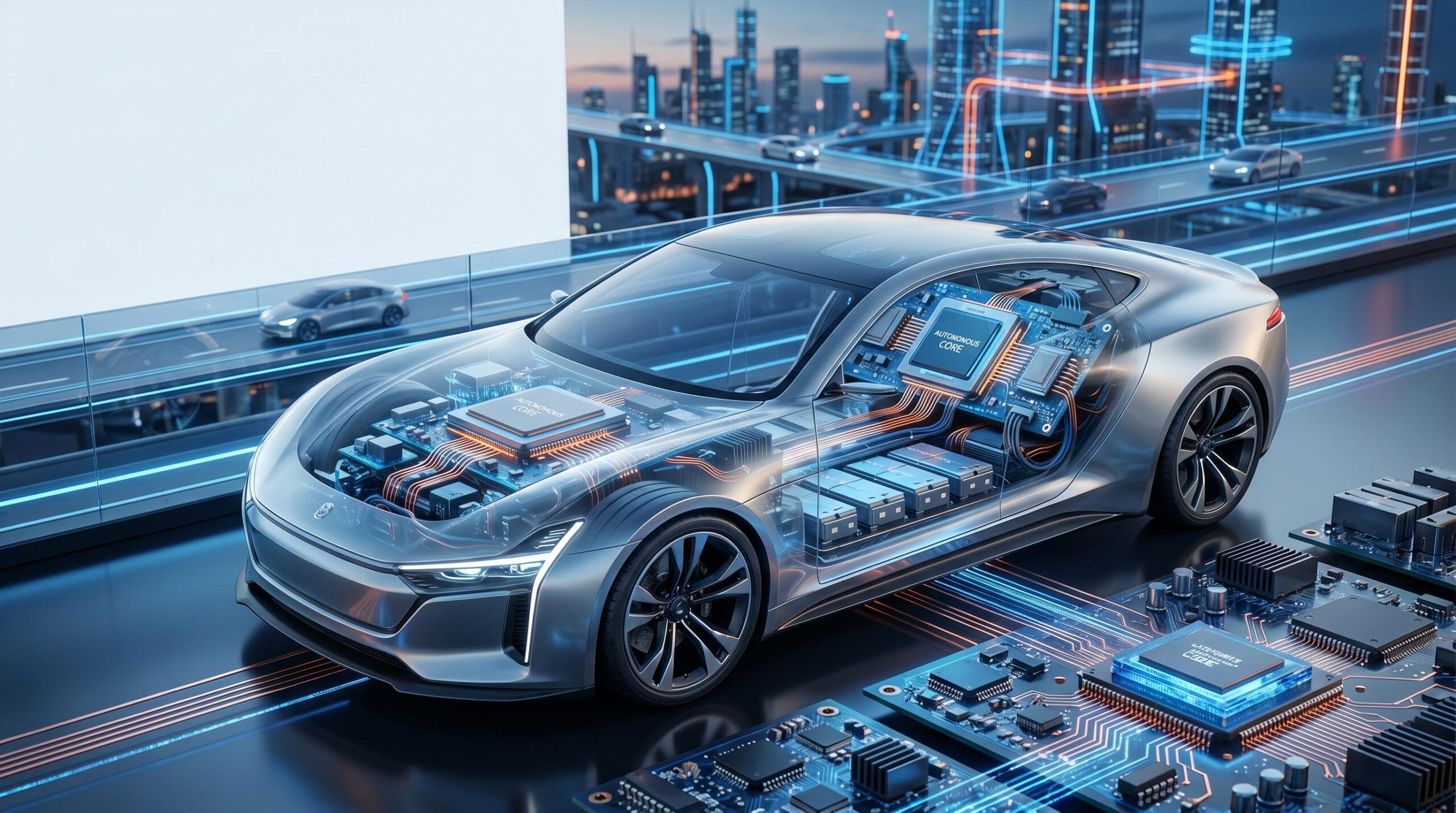
Tesla made a deliberate architectural bet on vision-only. The thesis, articulated publicly by Elon Musk, holds that human drivers navigate complex environments using binocular vision alone — so a sufficiently capable deep neural network running on camera data should replicate and eventually exceed human performance. Tesla’s current FSD compute platform, designated HW4 (colloquially AI4), runs a custom system-on-chip.
A 2023 third-party teardown — corroborated by Electrek’s November 2025 competitive analysis and Wikipedia’s Tesla Autopilot Hardware article — identified a Samsung-manufactured processor on a 7nm process node with 16GB of RAM and 256GB of onboard flash. The specific RAM type wasn’t confirmed. Tesla hasn’t published an official hardware specification. Still hasn’t.
Per Tesla’s safety page accessed May 2026, the FSD (Supervised) fleet has accumulated 10 billion cumulative miles — 3.7 billion on city street networks. By late April 2026, per Basenor citing Tesla’s safety dashboard, the fleet was logging approximately 29 million miles per day, up from 14 million at the start of the year.
Here’s something I’d flag for any B2B audience: mileage accumulation does not itself demonstrate safety performance. A Reuters investigation published May 28, 2026 — drawing on interviews with nine former Tesla data labelers, a former self-driving engineer, and 11 traffic-safety researchers — found that Tesla’s FSD safety statistics rely on flawed comparison methodology, including comparing airbag-deployment crash rates in FSD-piloted Teslas against federal datasets covering far less-severe incidents, and benchmarking against the average U.S. vehicle fleet, which is considerably older than the average Tesla. The 10 billion-mile figure is a factual accumulation metric. Safety conclusions drawn from it should be treated with that context firmly in mind.
Waymo went the other direction entirely. Their vehicles carry a redundant multi-modal stack: high-resolution cameras, millimeter-wave radar, and lidar. Lidar — Light Detection and Ranging — emits pulsed laser signals and measures time-of-flight returns to build a dense real-time 3D point cloud of the vehicle’s environment. Geometrically precise. Lighting-invariant in ways RGB camera imagery simply isn’t. The tradeoff is cost and compute. Industry estimates place Waymo’s multi-sensor hardware stack substantially above Tesla’s camera-only hardware cost — the directional gap isn’t disputed in the industry, though Waymo doesn’t publish hardware cost data, and specific figures from investor research firms shouldn’t be treated as authoritative.
Does the multi-modal stack justify the additional cost? The safety data makes a strong case. Per Waymo’s Safety Impact Hub at waymo.com/safety/impact (through December 2025), Waymo’s rider-only fleet logged 170.7 million driverless miles and showed a 92% reduction in insurance claims involving bodily injury and an 88% reduction in property damage insurance claims versus human drivers on the same road network — cross-validated by Swiss Re in Di Lillo et al.’s 2024 insurance claims analysis.
A peer-reviewed study in Traffic Injury Prevention (Kusano et al., 2025; doi:10.1080/15389588.2025.2499887), covering 56.7 million rider-only miles, found an 85% reduction in suspected serious injuries, with a 96% reduction in injury-reported crashes at intersections specifically. One methodological note that matters: AV incident reporting obligations under UNECE and NHTSA frameworks are broader than those applied to human drivers, and Waymo’s figures reflect performance within defined, geofenced operational design domains — not unrestricted road conditions globally. The peer-reviewed studies adjust for this asymmetry, but the comparison isn’t perfectly equivalent to an uncontrolled human driving population.
With that said — a 96% reduction at intersections, even within a defined ODD, is not incremental progress. That’s a qualitatively different safety outcome.
End-to-End Deep Learning and the Training Data Flywheel
Whether the platform is Tesla or Waymo, the inference engine executing real-time driving decisions is a deep neural network (DNN) trained end-to-end on real-world driving data. No explicit rule encoding. No hand-authored if-then logic. Engineers curate training datasets, define objective functions, and run large-scale gradient descent. The network learns a driving policy directly from data — including edge cases, weather conditions, and traffic scenarios no rules-based system could anticipate exhaustively.
The DNN ingests raw sensor tensors — camera pixel arrays, radar Doppler return matrices, lidar point clouds — and outputs a control policy: longitudinal acceleration command, lateral steering angle delta, and associated confidence estimates. What made this viable at vehicle scale was the maturation of ASIC and SoC design: inference hardware compact enough to fit in a vehicle compute enclosure, power-efficient enough to run within automotive thermal limits, and fast enough to meet real-time vehicle control loop latency requirements.
Tesla’s compounding advantage is training data volume. Every Tesla produced since 2016 has operated in shadow mode — the onboard FSD computer continuously runs inference and logs its predicted control outputs against observed driver behavior, even when Autopilot is disengaged. Per Tesla’s safety page, this produced 670 million FSD-engaged miles in 2023, 2.25 billion in 2024, and 4.25 billion in 2025 (Teslarati, March 2026).
Waymo accumulated approximately 71 million rider-only miles through March 2025 per Contrary Research’s July 2025 analysis — a smaller number, but generated entirely without a human driver in the loop. Different scale. Different validation signal. Different bet entirely.
Tesla’s next-generation inference platform, AI5, was taped out April 15, 2026, per Elon Musk’s post on X, corroborated by Electrek and electric-vehicles.com.
Designed to deliver approximately five times the useful compute of the current dual-SoC AI4 configuration. But — and this gets missed in the headlines — it isn’t going into consumer vehicles first. Initial deployment targets are the Optimus humanoid robot platform and Tesla’s internal supercomputer clusters. (Note: Dojo uses a separate custom D1 chip architecture; AI5 deployment to internal compute infrastructure was confirmed by Musk without specifying Dojo by name.) Vehicle integration isn’t expected until mid-to-late 2027. The Cybercab launching Q2 2026 ships on AI4. Not AI5. AI4.
How the EV Transition Rewrote Automotive PCB Engineering
High-Voltage Domain Isolation: A New Design Constraint
The electrification of the powertrain did not simply replace a combustion engine with a battery pack. It changed the fundamental electrical operating environment of the vehicle — and that change propagates through every PCB design decision made anywhere in the system.
To be honest, this is the part most coverage completely skips. Traditional 12V automotive electrical architectures operate within well-characterized insulation coordination parameters. Creepage and clearance at 12V are manageable. EMC profiles are predictable. Failure modes are understood. EV traction systems operate at 400V to 800V DC bus voltages per IWD Fluid Solutions’ automotive PCB design guide (February 2026). At those potential differences, a single dielectric failure — inadequate creepage distance, a contaminated conformal coating, a compromised solder joint — isn’t a component fault. It can initiate sustained arc faults, thermal runaway in adjacent cells, or catastrophic insulation breakdown.
That’s the stakes.
This is why automotive PCB design now mandates reinforced isolation architecture between HV and LV domains: physical board separation with defined air gaps, conformal coating with materials qualified per IPC-CC-830 (which defines material performance requirements including dielectric withstand voltage, moisture resistance, and chemical stability); coating coverage and workmanship acceptability evaluated per IPC-A-610 (visual acceptability of electronic assemblies) with application process requirements defined in IPC-J-STD-001; creepage and clearance calculations substantiated per IEC 60664-1 — the international standard governing insulation coordination for low-voltage equipment.
I’ve found that engineers moving from conventional automotive electronics into EV platform work frequently underestimate how significantly this shifts the automotive PCB design methodology. The insulation coordination problem alone adds substantial design and verification overhead that simply didn’t exist in 12V architectures.
The Battery Management System: Safety-Critical Embedded Controller
Every EV carries a Battery Management System. Most people have never heard of it. From a functional safety architecture standpoint, it is among the most demanding embedded controllers in the vehicle — and it gets a fraction of the coverage the autonomy stack receives. The automotive PCB design requirements for the BMS alone would fill an engineering handbook.
The BMS is a dedicated embedded controller PCB with one job: continuous real-time monitoring and active management of every cell in the traction battery pack. Individual cell voltage. Temperature gradient across the pack. State-of-charge (SOC). State of health (SOH). Internal impedance drift over cycle life. Charge/discharge current limits.
It executes active and passive cell balancing algorithms — passive balancing dissipating excess charge energy as heat through resistive elements, active balancing redistributing charge between cells to maximize usable pack capacity. It issues thermal throttling commands to the vehicle’s thermal management system and transmits diagnostic data to higher-level vehicle control modules over the CAN or Ethernet backbone.
The operating environment is genuinely unforgiving. Extended automotive temperature grade: -40°C to +85°C continuous, with transient excursions beyond those bounds. Constant mechanical vibration per ISO 16750-3 road load profiles. Ten to fifteen years of field life required. Zero tolerance for undetected failures in safety-critical functions. Zero.
Semiconductor components must be qualified to AEC-Q100 stress test requirements. Functional safety under ISO 26262 is applied through safety goal decomposition: isolation monitoring and thermal runaway detection — the functions where failure can directly cause injury or fire — are typically assigned ASIL-D, the highest Automotive Safety Integrity Level in the standard.
Lower-criticality BMS functions such as SOC estimation and passive balancing carry lower ASIL ratings or QM (Quality Management) classification. The BMS is not a single monolithic ASIL-D device. It’s a system whose safety architecture must be carefully decomposed, with each function assigned an integrity level proportional to its contribution to potential harm.
Your laptop is designed for a three-year service life in a climate-controlled environment. The BMS operates in an electrochemical system capable of thermal runaway, in a vehicle exposed to road salt, vibration, and temperature extremes, for fifteen years. Not the same standard. Not close. Not remotely.
Automotive PCB Design: The Unwritten Hardware Story
Market Scale and Architectural Complexity
The automotive PCB design industry doesn’t generate the headlines that chip fabs and autonomy software stacks do. But the market data reflects its centrality to the EV and AV transition directly. BCC Research values the global PCB market at $67.9 billion in 2023, projecting growth to $92.4 billion by 2029 at a 5.4% CAGR, with EV adoption and autonomous vehicle deployment identified as primary demand drivers. EV-specific segment projections vary by analyst methodology, but the directional signal is consistent.
Think about the board count in a fully modern vehicle. The traction inverter carries its own gate driver PCB, executing the IGBT or SiC MOSFET switching sequences that convert DC bus power to AC motor drive. The ADAS domain controller runs camera ISP pipelines, radar signal processing, and lidar point cloud preprocessing on dedicated compute boards. The infotainment SoC. The instrument cluster MCU. The adaptive lighting driver. The BMS. The body control modules. The gateway ECU managing inter-domain communication.
Each is a distinct board-level design with its own power delivery, signal integrity, and thermal management requirements. Above all of that sits the autonomous driving computer — a high-power compute board running the DNN inference workloads that execute the driving policy. As vehicle autonomy levels advance and functional consolidation shifts toward centralized domain controllers and zonal E/E architectures, per-board complexity increases even as total ECU counts decrease in some implementations. There is no trajectory in the software-defined vehicle roadmap that requires fewer circuit boards. None. It only goes one way. More boards. More complexity. Every generation.
Thermal Management: The Core Constraint in Automotive PCB Design
Ask any experienced automotive PCB design engineer what separates automotive board design from consumer electronics design. The conversation arrives at thermal management within the first few minutes. Every single time. It is not an afterthought. It is not a late-stage optimization. It is a first-order constraint in automotive PCB design that shapes layout, component selection, copper weight, stackup, and mechanical packaging from the earliest design phases.
High-power switching electronics — traction inverters, DC/DC converters, onboard chargers, the BMS itself — generate substantial thermal loads. A power semiconductor operating within datasheet specifications at 25°C ambient can experience early life failure at 105°C junction temperature under sustained duty cycle.
Automotive PCBs must maintain electrical and mechanical integrity through thousands of thermal cycles: traces must not delaminate, solder joints must not develop fatigue fractures, and the PCB substrate must not exceed its glass transition temperature (Tg) under worst-case thermal loading. These are not conservative design margins. They are the minimum acceptable performance envelope for a safety-critical product with a 10- to 15-year field life.
This is why thermal simulation runs as a required design gate before any physical prototype is committed to fabrication. Tools like Siemens FloTHERM, Ansys Icepak, or Cadence Celsius (increasingly adopted for electro-thermal co-simulation integrated directly with PCB layout environments) are used to model the complete thermal network: conductive pathways through copper pours and thermal via arrays, convective transfer to heatsinks and enclosure walls, radiative exchange with the surrounding thermal environment. Hotspot identification drives iterative layout changes. Before a single board is manufactured.
Catching this at simulation costs engineering hours. Catching it in production validation costs tooling cycles, schedule, and potentially a field safety event. Siemens publishes simulation-driven development methodology guidance specifically for EV power electronics design — because getting it wrong doesn’t just cost a prototype. It costs a production tooling cycle.
Electromagnetic Compatibility: The Cross-Domain Interference Problem
Pack high-voltage power electronics and sensitive low-voltage signal processing electronics into the same enclosure. What do you get? An EMC challenge that has no precedent in conventional 12V automotive architecture.
The traction inverter — executing high-frequency switching of 400V to 800V DC bus power to synthesize the AC drive waveform for the traction motor — is a broadband conducted and radiated EMI source. The switching harmonics propagate through the vehicle’s HV wiring harness and radiate from the power electronics enclosure.
In a modern EV, the electronics most susceptible to those emissions sit in close proximity: ADAS camera serializer/deserializer (SerDes) links operating at multi-gigabit data rates, GNSS receivers with microvolt-level signal sensitivity, CAN/LIN/Ethernet transceivers, and the safety-critical ECU communication interfaces. Disruption of any of these by EMI from the traction system isn’t merely a nuisance. In a vehicle executing autonomous driving functions, it is a potential functional safety hazard.
Managing this requires rigorous EMC design discipline at the board, module, and system levels simultaneously: controlled impedance routing for high-speed differential pairs, continuous ground plane management, strategic placement of common-mode chokes and ferrite bead filters, shielding enclosure design, deliberate physical domain separation between HV power electronics and LV signal-processing assemblies. EMC pre-compliance testing in a shielded anechoic chamber or TEM cell environment is now a standard milestone in automotive electronics development programs — a gate that didn’t exist when the most electromagnetically aggressive system in the vehicle was the ignition system.
Automotive Cybersecurity: The Regulatory Layer Nobody Can Ignore
The Compliance Landscape Has Fundamentally Shifted
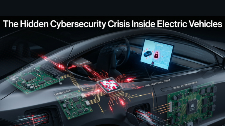
A software-defined vehicle that ships FSD updates over the air and maintains a persistent cellular connection to a backend cloud infrastructure is not just an engineering achievement. It is an attack surface. And as of July 2024, regulators in UNECE member states made clear that managing that attack surface is no longer optional.
Two UNECE WP.29 regulations now govern vehicle cybersecurity across Europe, Japan, South Korea, and adopting markets. UNECE R155 mandates that OEMs establish and maintain a Cybersecurity Management System (CSMS) — a documented organizational framework covering cybersecurity risk governance, threat monitoring, incident response, and lifecycle management from vehicle concept through decommissioning.
As of July 2024, R155 compliance is a condition of vehicle type approval for all new vehicles entering production in UNECE member states. Per Upstream Security’s 2024 regulatory analysis, some OEMs discontinued specific models rather than absorb the compliance cost (not because R155 alone was prohibitive, but typically because legacy E/E architectures and low-volume platforms made the combined R155/R156 compliance burden unworkable).
UNECE R156 addresses Software Update Management Systems (SUMS) — ensuring that OTA updates are cryptographically authenticated, integrity-verified, and incapable of introducing new attack vectors into the vehicle. Manufacturers must obtain SUMS certification from an approval authority, valid for three years, with continuous monitoring required to maintain it.
One thing worth flagging for engineers outside the UNECE-ratified world: R155/R156 don’t apply everywhere. China governs vehicle cybersecurity through its own GB/T standards (GB/T 38628 and related regulations). The United States uses a combination of NHTSA voluntary guidance and NIST cybersecurity framework alignment rather than mandatory type-approval requirements. Engineers at Detroit or Shanghai facilities operate under materially different compliance regimes — that distinction matters.
ISO/SAE 21434:2021, published jointly by ISO and SAE International, provides the engineering framework OEMs and their Tier 1 and Tier 2 suppliers use to operationalize R155 compliance. Unlike R155, it isn’t legally binding — but it has become a de facto contractual requirement across the automotive supply chain, per Code Intelligence’s 2024 compliance analysis.
The core methodology it mandates is TARA — Threat Analysis and Risk Assessment. Under ISO/SAE 21434, every item in the vehicle E/E system — whether assessed at system, subsystem, or ECU level — requires a TARA as part of the cybersecurity development process. The granularity of TARA implementation varies by architecture; what’s consistent is that no safety- or security-relevant item reaches production without a documented threat analysis and risk assessment.
The OTA Attack Surface: Why R156 Is as Important as R155
Here’s the thing most automotive cybersecurity coverage misses: the OTA update capability that makes Tesla’s software improvement model possible is simultaneously the highest-consequence attack vector in the vehicle. A compromised OTA update pipeline — one that allows an adversary to push unauthorized firmware to the FSD compute platform, the BMS, or a safety-critical ECU — represents a remote code execution vector with physical-world consequences at vehicle scale.
UNECE R156 addresses this directly. Cryptographic signing of all software packages. Integrity verification at the vehicle before any update lands. Rollback capability for failed or malicious updates. Audit logging across the fleet. All of it. ISO 24089, which complements R156 at the engineering process level, provides detailed guidance on software update engineering methodology — update planning, package development, staged deployment, post-deployment monitoring.
I’ve found the convergence of ISO 26262 (functional safety) and ISO/SAE 21434 (cybersecurity) particularly worth flagging for a B2B engineering audience. The two standards are complementary by design: a vulnerability that allows an attacker to disable a safety function — inhibiting ABS actuation, spoofing BMS cell voltage readings, injecting false lidar point cloud data into the ADAS fusion pipeline — is simultaneously a cybersecurity incident and a functional safety event.
Designing for both simultaneously, from the earliest concept phases, is now the expected baseline for any E/E system going into production. To be direct about it: it’s substantially harder than designing for either standard alone.
What This Means for the PCB Engineering Stack
Cybersecurity requirements don’t live only in software. They cascade into hardware. All the way down to the board.
Secure boot — the chain-of-trust mechanism that cryptographically verifies each stage of the firmware load sequence before allowing the processor to execute — requires a hardware root of trust: typically implemented as an integrated Hardware Security Module (HSM) within the SoC’s boot ROM and fuse-blown key infrastructure, or supplemented by a discrete secure element (SE) or Trusted Execution Environment (TEE) as a companion device on the PCB. Integrated HSM implementations provide the strongest security posture; discrete SE approaches offer flexibility but must be carefully architected to avoid introducing additional attack surface.
Key storage, attestation, and cryptographic acceleration are hardware functions, implemented on silicon, sitting on automotive-grade circuit boards that must be physically tamper-evident and meet AEC-Q100 qualification requirements for the semiconductor components they carry.
The design implication is direct. Good automotive PCB design for a safety- or security-relevant ECU must simultaneously satisfy thermal management requirements (junction temperature, thermal cycling endurance), EMC requirements (HV/LV isolation, controlled impedance routing), functional safety requirements (ISO 26262 ASIL compliance, redundancy architecture), and cybersecurity hardware requirements (HSM integration, hardware root of trust, tamper evidence). These are not independent constraints.
They interact. Every one of them. And resolving those interactions at the board level — within automotive power and space envelopes, with AEC-Q100-qualified semiconductor components, against a 15-year field life mandate — is where the real complexity of modern automotive PCB engineering actually lives.
What This Means for the Engineering Profession and the Road Ahead
The software-defined vehicle is not a future state. It’s here. Now. It is the present state of the automotive industry’s technology frontier. Tesla distributes FSD inference model updates over-the-air; the vehicle’s driving policy improves between trips without a service visit or hardware change. Waymo retrains and redeploys its autonomy stack across entire operational design domains (ODDs) without modifying vehicle hardware. The physical vehicle is the substrate. The software — and the silicon executing it — is the product roadmap.
For the engineering community, this is restructuring career trajectories and team compositions. In ways that weren’t predictable five years ago. PCB layout engineers are expected to understand AI accelerator power delivery and thermal envelope requirements. Machine learning engineers are expected to understand AEC-Q100 qualification timelines and ISO 26262 ASIL decomposition. Embedded systems engineers are expected to reason about DNN inference latency budgets and functional safety architecture simultaneously. These competency domains were largely siloed five years ago. They are merging at pace.
And the public health dimension of all this? It’s significant and underappreciated. Per NHTSA’s Early Estimate of Motor Vehicle Traffic Fatalities in 2024 (DOT HS 813729, May 2025), 39,345 people died in U.S. road crashes in 2024 — the lowest fatality rate per 100 million vehicle miles traveled (1.20 VMT) since before the pandemic, but still nearly 40,000 lives.
If autonomous systems can be deployed at scale while sustaining safety outcomes consistent with Waymo’s peer-reviewed published data, the public health arithmetic shifts materially. That assessment carries all appropriate caveats — operational domain constraints, edge case generalization, regulatory framework development, the difference between controlled deployment and unrestricted nationwide operation. The data is directionally compelling. The engineering work to realize it at scale remains substantial. Very substantial.
The hardware running today’s production vehicles already represents a remarkable engineering achievement. Genuinely remarkable. What comes next — AI5-class inference silicon in volume production vehicles, full-stack autonomy across unrestricted operational domains, 800V EV architectures, and, if solid-state battery technology reaches volume production (multiple manufacturers have announced timelines; no volume production vehicle had shipped with solid-state cells as of May 2026), the PCB and BMS design requirements that will accompany it — will demand more. The automotive PCB design engineers, power electronics designers, functional safety architects, and silicon teams building that hardware are defining what transportation looks like for the next generation.
About the Author
Imran Valiani | Sales Director, PCB Electronics Manufacturing — 20+ years working with major Bay Area and global tech clients. Founder of Silicon to Software, where I write about the hardware layer — PCB fab, AI gear, autonomous systems, and cyber — the stuff most tech writers have never touched. Literally. Follow: X @SiToSoftware | LinkedIn
This post was written with AI assistance. See my full AI disclosure.
References
- Tesla, Inc. Tesla Vehicle Safety Report. tesla.com/safety. Accessed May 2026.
- Teslarati. “Tesla FSD (Supervised) fleet passes 8.4 billion cumulative miles.” March 2026. Basenor. “Tesla FSD Hits 9 Billion Miles.” April 2026.
- Wikipedia contributors. “Tesla Autopilot hardware.” Citing August 2023 teardown by @greentheonly. Electrek. “Tesla AI4 vs. NVIDIA Thor: the brutal reality of self-driving computers.” November 25, 2025.
- Elon Musk. Post on X (formerly Twitter), April 15, 2026. EV (eletric-vehicles.com). “Tesla Tapes Out AI5 Chip.” April 2026. Electrek. “Tesla taped out AI5 chip, Musk says.” April 15, 2026.
- Waymo LLC. Waymo Safety Impact Hub. waymo.com/safety/impact. Through December 2025.
- Di Lillo, L., Gode, T., Zhou, X., Scanlon, J. M., Chen, R., & Victor, T. (2024). “Do Autonomous Vehicles Outperform Latest-Generation Human-Driven Vehicles? A Comparison to Waymo’s Auto Liability Insurance Claims at 25.3M Miles.” Waymo LLC / Swiss Re.
- Kusano, K. D., Scanlon, J. M., Chen, Y. H., McMurry, T. L., Gode, T., & Victor, T. (2025). “Comparison of Waymo Rider-Only Crash Rates by Crash Type to Human Benchmarks at 56.7 Million Miles.” Traffic Injury Prevention, 26(sup1), S8–S20. doi:10.1080/15389588.2025.2499887
- Contrary Research. “Tesla, Waymo, and the Great Sensor Debate.” July 8, 2025. research.contrary.com
- National Highway Traffic Safety Administration. Early Estimate of Motor Vehicle Traffic Fatalities in 2024. DOT HS 813729. April 2025. crashstats.nhtsa.dot.gov
- BCC Research. Printed Circuit Boards: Technologies and Global Markets. 2024. bccresearch.com
- Wikipedia contributors. “Electronic control unit.” en.wikipedia.org/wiki/Electronic_control_unit. Precedence Research. Automotive Electronic Control Unit Market Size Report. precedenceresearch.com
- IWD Fluid Solutions. “Automotive PCB Design Guidelines.” iwdfsolutions.com. February 2026. Siemens. “Digitalizing Development of Electric Vehicle Electronics.” Siemens EDA White Paper. resources.sw.siemens.com
- Automotive Electronics Council. AEC-Q100: Failure Mechanism-Based Stress Test Qualification for Integrated Circuits. jedec.org. International Organization for Standardization. ISO 26262: Road Vehicles — Functional Safety. iso.org
- arxiv.org. “Moving Forward: A Review of Autonomous Driving Software and Hardware Systems.” November 2024. arxiv.org/abs/2411.10291