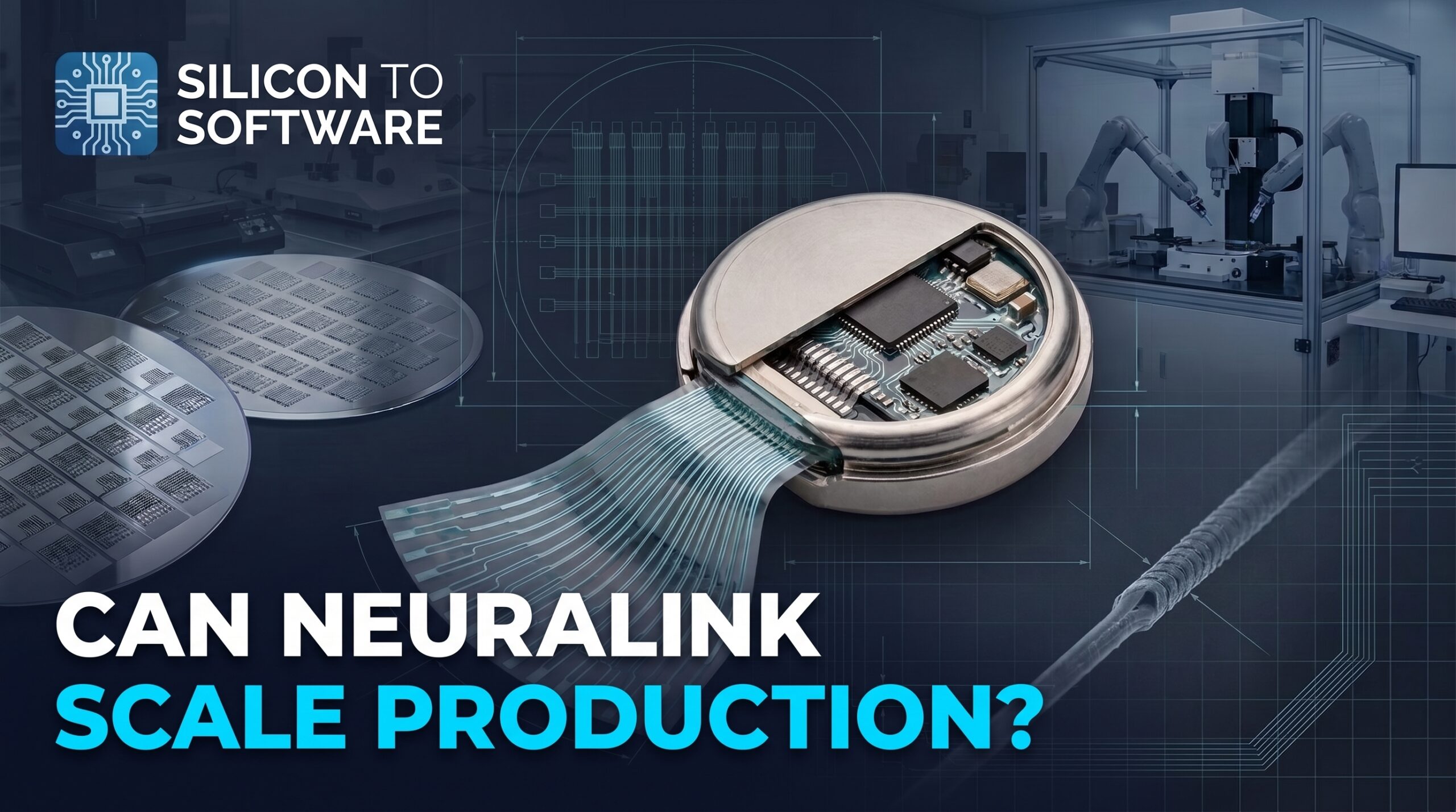
Neuralink Wants to Mass-Produce Brain Implants. Here’s the Engineering Challenge.
From ultra-thin electrode threads to moisture barriers and manufacturing yield, scaling brain implants demands more than a working prototype.
Current as of October 2026.
On December 31, 2025, Elon Musk posted that Neuralink would start high-volume production of its brain-computer interface devices in 2026 and move to an “almost entirely automated surgical procedure” the same year. It was a stated plan, not a production report.
By mid-October 2026, I had not found production volume or manufacturing capacity in any primary Neuralink source I reviewed. What is public is evidence of investment. A Texas state filing registered in February 2026 lists Neuralink Corporation as owner of an estimated $8.2 million tenant improvement of existing shell space for office and manufacturing use, covering 37,607 square feet at its Del Valle site.
An earlier filing for the same site describes a new three-story, 112,000-square-foot building with offices, a machine shop, and cleanroom device manufacturing. The Austin Business Journal also reported that Neuralink’s job listings included software engineers to improve its implant manufacturing line and testing software.
Filings and hiring show investment. They don’t show output. The absence of public production data is not evidence that Neuralink has failed to scale. It means outside observers can’t independently quantify that scale.
That gap, between a stated plan and public evidence of Neuralink mass production, is where the engineering lives. A brain implant that works in a limited number of trial participants and one that can be manufactured, verified, and implanted reliably at volume are separate achievements, and each needs its own evidence. This article examines what has to be true for any company to scale an implantable brain-computer interface, and what the public record does and doesn’t establish about Neuralink. For how the N1 implant works, see Neuralink Brain Chip Explained: What the Hardware Actually Does Inside the Human Brain.
My perspective comes from more than 20 years in PCB and electronics manufacturing. The challenges of fine-feature fabrication, assembly yield, inspection, and scaling production have useful parallels here. Implantable medical devices also introduce requirements that conventional PCB manufacturing does not address.
Table of Contents
What “High-Volume” Could Mean: Four Numbers That Get Blurred
“High-volume production” can refer to at least four different quantities:
- Manufacturing capacity: how many units a factory could build.
- Regulatory authorization: what the device is lawfully permitted to be used for.
- Clinical enrollment: how many people the trials enroll. The most recent figure I could locate from Neuralink itself is from January 28, 2026, when the company said it had 21 participants enrolled in trials worldwide. A registration statement filed with the SEC by ClearOne Inc., a third party, cites public statements to report that Neuralink had 26 participants enrolled globally as of June 30, 2026. I have not located the underlying Neuralink statement. Neither figure should be read as a verified current total.
- Surgical throughput: how many procedures can be performed, given sites, surgical teams, patient screening, and the robot. Neuralink’s registered feasibility and early-feasibility studies span sites in the United States, Canada, the United Kingdom, and the UAE. The U.S. PRIME study lists Barrow Neurological Institute and the University of Miami.
In the United States, an approved Investigational Device Exemption (IDE) lets a device that would otherwise need premarket approval or a performance standard be shipped lawfully for the purpose of investigating it. It is not authorization for commercial distribution. Neuralink has not publicly confirmed which marketing pathway it intends to pursue.
A factory can build more units than trials are permitted to use. Musk’s post doesn’t say which of the four numbers “high-volume” refers to, and the public record doesn’t settle it.
Why an Implant Isn’t a Consumer-Electronics Scale-Up
Consumer electronics makers run serious reliability programs. The discipline is related. What changes is the environment, the consequence of failure, and the burden of evidence:
- Environment. The device operates continuously in warm, ionic, chemically active tissue that responds to foreign material.
- Consequence. Some malfunctions can be managed in software. When revision or removal is needed, it carries surgical risk.
- Evidence. Reliability must be demonstrated before broad use, with limited ability to learn from field returns.
Reuters reported in 2023, citing seven current and former Neuralink employees, that the FDA had rejected Neuralink’s initial human-trial application in 2022 over safety concerns involving the lithium battery, possible migration of the implant’s wires to other areas of the brain, and whether the device could be removed without damaging brain tissue. Each of those is an engineering problem.
Electrode Threads: What Fabrication Has to Get Right
What Neuralink has documented
Neuralink’s current technology page says the implant records neural activity through highly flexible, ultra-thin electrode threads, too fine to be inserted by the human hand, which a surgical robot places.
The most detailed public description of thread construction from a research system is Neuralink’s 2019 peer-reviewed white paper in the Journal of Medical Internet Research. In that system, polyimide served as substrate and dielectric, encapsulating a gold thin-film trace, with nominal thickness of 4–6 µm, including up to three insulation layers and two conductor layers. Each thread carried 32 independent electrodes.
That research system is not today’s device. In a published PRIME Study Progress Update (April 2024), Neuralink described the N1 Implant as recording through 1,024 electrodes distributed across 64 flexible threads, and said it fabricates the thin-film microelectrode arrays that form those threads in-house on silicon wafers.
In an August 2024 interview on the Lex Fridman Podcast, Neuralink executive DJ Seo described that configuration as 16 electrodes per thread. He described each thread as about 16 µm wide and under 5 µm thick: roughly 2 µm of polyimide, a 400 nm titanium–platinum–gold–platinum–titanium metal stack, and another 2 µm of polyimide, with metal conductors about 2 µm wide.
These are company descriptions of the device at that time. They are not verified current production specifications or independent confirmation of the configuration used in every current implant. Neuralink’s current technology page does not specify electrode or thread counts, and I could not find a published process flow or complete current layer stack.
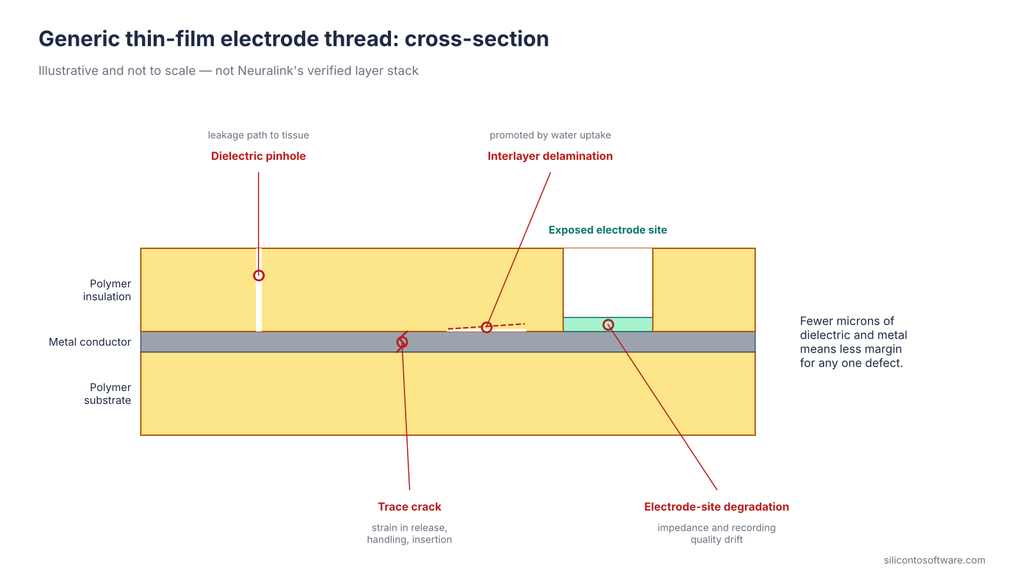
Thin-film failure mechanisms
At a few microns thick, the familiar failure modes have little margin:
- Dielectric pinholes open leakage paths to tissue or between traces.
- Trace cracking results from strain during release, handling, or insertion.
- Interlayer delamination at metal–polymer interfaces is promoted by water uptake.
- Electrode-site degradation shifts impedance and recording quality over time.
All else equal, thinner threads flex more and displace less tissue, though bending stiffness also depends on width, modulus, and layer stack. Thinner threads also leave less dielectric and mechanical margin, so a defect that a thicker structure would tolerate can end a channel.
Where the PCB parallel holds, and where it breaks
In flex-circuit manufacturing, opens and cracks concentrate at bend zones and fine features, and particulate control drives fine-line yield. For the board-level version of how small, repeatable design oversights erode yield, see 5 Common PCB DFM Mistakes That Can Reduce Fabrication and Assembly Yield.
The parallel stops at the process. IPC-6013, now in Revision F (2026), covers qualification and performance requirements for flexible printed boards designed to IPC-2221 and IPC-2223. In my interpretation, the 2019 research threads, a 4–6 µm multilayer thin film patterned with stepper lithography, sit closer to microfabrication than to conventional flex. PCB qualification norms don’t map onto them directly.
The 2019 paper also includes a company-reported comparison between two research configurations. Neuralink reported that the lower-channel System A was designed for faster, more reliable manufacturing and could be built five times faster than the denser System B, with better yields. The two differed in more than electrode count: System B was designed to maximize channel density and used an earlier ASIC revision with poorer performance specifications. So the comparison doesn’t isolate channel count. It does show that the density-versus-manufacturability tension was present at the research stage.
Thread Handling and Assembly: A Separate Yield Problem
Fabricating a thread and getting it intact into a finished device are different problems. The 2019 paper describes three distinct steps:
- Pre-insertion handling. Parylene-C was deposited to form a film the threads stayed attached to until the surgical robot pulled them off.
- Assembly to electronics. Gold stud bumps on a printed circuit board served as alignment guides; the thin film was placed over them, and the bumps were flattened into rivets. Chips were then flip-chip bonded to both the thin-film contacts and the PCB pads.
- Manufacturing partner. Thread manufacturing and high-density package assembly were done in collaboration with Lawrence Livermore National Laboratory.
All three describe the 2019 research system. The N1’s assembly process is not public.
For a PCB audience, the research package is a familiar construction at an unfamiliar scale: a printed circuit board, flip-chip attach, and a polymer flex structure mechanically registered to it. The risk is familiar too. Handling damage is often latent. In an illustrative scenario, a partially cracked trace passes continuity at final test and opens later. Nothing public shows this in the N1, but that class of defect is among the hardest to screen in fine-pitch assembly.
Moisture Barriers and Implant Packaging
What Neuralink says
Neuralink’s technology page describes the implant as hermetically sealed in a biocompatible enclosure that withstands physiological conditions several times harsher than those in the human body.
In the August 2024 interview, DJ Seo described the enclosure as using PCTFE (polychlorotrifluoroethylene), a polymer selected in part for its electromagnetic transparency during inductive charging. He contrasted it with the laser-welded titanium cans common in medical implants, which he said would need a sapphire window to allow that kind of charging, a process he called very tough to scale. This is a company representative’s description of the device at that time, not a complete published specification of the current enclosure or its hermetic sealing architecture. The identification of PCTFE does not, by itself, establish the complete hermetic barrier design or demonstrate its long-term leak-tightness.
Neuralink’s April 2024 update also shows a custom accelerated lifetime testing system that immerses implants in an environment harsher than in vivo conditions, without specifying those conditions. In the sources reviewed here, Neuralink has not provided enough information to establish the full sealing method, how the threads connect to the sealed electronics, or the qualification conditions behind “several times harsher.” I won’t infer them.
The 2019 paper shows how the company framed the problem early on. The rodent systems used titanium cases coated with parylene-C as a moisture barrier, and the authors wrote that the fully implantable clinical devices would require hermetic packaging.
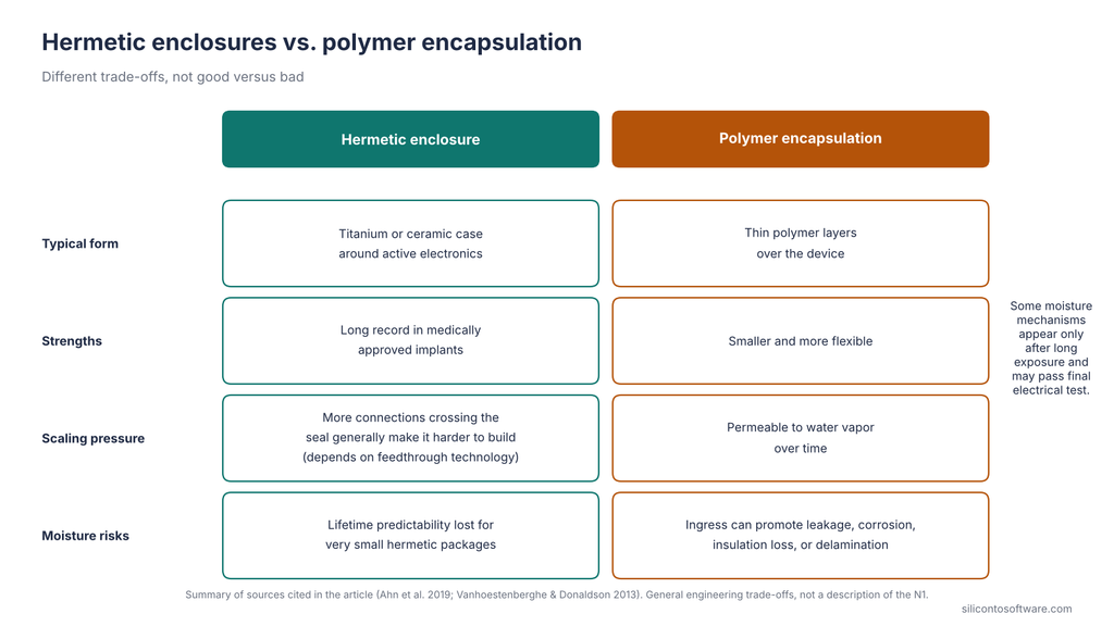
Hermetic enclosures versus encapsulation
A 2019 peer-reviewed review notes that medically approved implantable devices have relied on titanium or ceramic cases for hermetic encapsulation of active electronics. High channel counts strain that approach. The more electrical connections that must cross a hermetic boundary, the harder the boundary generally is to build, depending on architecture and feedthrough technology.
The N1’s interconnect architecture, including how many connections cross its seal, has not been published. Cardiac-device patent literature describes feedthroughs as a large share of manufacturing cost, a miniaturization limit, and a significant source of assembly reliability defects. That is a patent applicant’s characterization, not a survey.
Hermetic versus polymer isn’t good versus bad. A Journal of Neural Engineering analysis showed that lifetime predictability is lost for very small hermetic packages, and concluded that both hermetic packages and encapsulation may suit future implants. Polymers are smaller and more flexible, but they are permeable to water vapor over time.
Depending on the packaging materials and defect structure, moisture ingress can promote ionic leakage, corrosion, insulation degradation, or interfacial delamination. These mechanisms don’t necessarily occur in a fixed sequence. Some emerge only during prolonged exposure and may not be detected by final electrical testing.
How reliability evidence is built
No single method establishes multi-year implant reliability. Four complementary methods contribute:
- Accelerated aging. Encapsulation reliability is generally evaluated by soaking samples in saline at elevated temperature. Turning the result into a service-life estimate requires evidence that accelerated and physiological conditions produce comparable failure mechanisms, together with justified kinetic parameters. An Arrhenius extrapolation is only as good as those assumptions (engineering principle). The soak also departs from the body. One peer-reviewed study notes that, under its 87 °C test conditions, phosphate-buffered saline (PBS) became nearly oxygen-free, failing to reproduce the chemical environment around implants.
- Reactive accelerated aging. This complementary method was developed by FDA researchers to model oxidative degradation. In their 2015 study, microelectrode arrays sat in hydrogen peroxide at 87 °C for seven days, and physical changes were correlated with impedance data to identify failure markers. It targets specific mechanisms and doesn’t reproduce micromotion or the full foreign-body response.
- Qualification testing and failure analysis. These turn bench and explant failures into design and process corrections.
- Longitudinal clinical outcomes. These are the direct measure. As of October 2026, no participant has carried a Neuralink device for three years, given the reported January 2024 first implant.
Sterilization validation and biological evaluation under the applicable ISO 10993 standards also have to hold up as production scales. Neuralink has not disclosed its approaches to either. For how established implants approach hermetic sealing and biocompatibility, see Implantable Medical Devices: 7 Breakthrough Truths That Will Change How You Think About Healthcare.
Accelerated methods shorten development and screen out weak designs. Long-term human outcomes remain the reference they are checked against.
Testing a Sealed 1,024-Channel Implant
Once a device is sealed, inspection relies on electrical proxies: impedance, continuity, and insulation leakage. These can detect certain defects present at test, not mechanisms that haven’t happened yet. It’s the same gap between time-zero testing and field survival I covered in Industrial IoT Hardware Reliability: Why Boards That Pass Lab Testing Still Fail on the Factory Floor. That leaves a definitional question at the center of production: what counts as a passing device?
An illustrative yield model
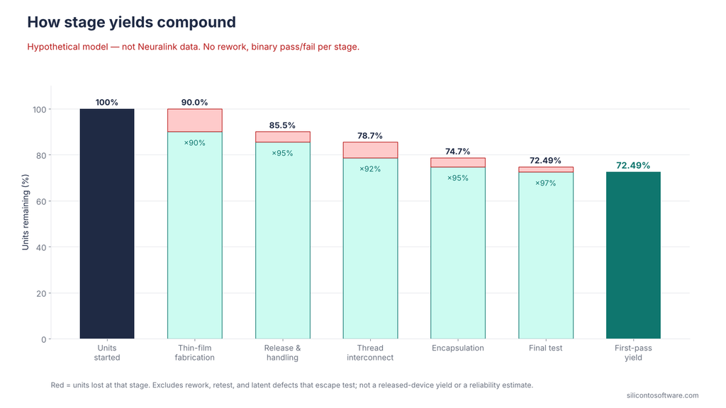
Hypothetical model. None of these numbers are Neuralink data. I could not locate publicly disclosed N1 manufacturing yields, stage structure, or acceptance criteria.
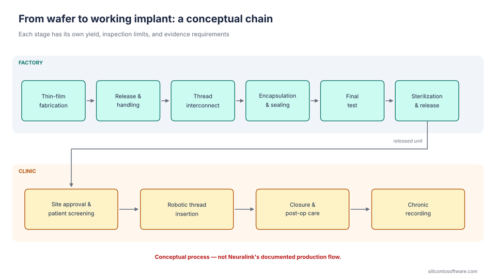
Stage compounding. Each stage yield is the fraction of units entering that stage that pass. Multiplying these conditional yields gives the overall yield, assuming binary pass/fail outcomes and no rework. Statistical independence between stages is not required. The result is a first-pass figure. It excludes rework, retest, and latent defects that escape test, and it is not a released-device yield or a reliability estimate.
| Stage (hypothetical) | Yield |
|---|---|
| Thin-film fabrication | 90% |
| Release and handling | 95% |
| Thread interconnect | 92% |
| Encapsulation | 95% |
| Final test | 97% |
| Illustrative no-rework first-pass yield | 72.49% |
Channel compounding. For this illustration, a “channel” is one electrode site and its signal path, and a passing channel is one that satisfies a hypothetical electrical acceptance test. Passing that test does not mean the channel will record usable neural activity after implantation. Neuralink reported recording quality separately in its 2019 paper as spiking yield: 43.4% of channels on one array and a maximum of 70% across others. That is a different measure from electrical function and should not be compared with the figures below.
Assume each channel independently has a 99.9% probability of passing. That is an independent, identically distributed binomial model.
| Channels | All channels pass | Five or fewer fail (hypothetical criterion) |
|---|---|---|
| 1,024 | 35.90% | 99.93% |
| 3,000 | 4.97% | 91.62% |
The five-channel threshold is invented for the example. It is not a proposed specification for Neuralink or any clinical implant. The “all pass” column is a perfect-channel metric, not clinically acceptable yield. Real acceptance can involve impedance, leakage, noise, spatial distribution, and redundancy, not only a count of failures. Five dead electrodes spread across recording regions may matter less than five concentrated in one functionally important region.
A similar yield-compounding problem appears in MicroLED manufacturing, where millions of microscopic emitters must all work.
Correlated failures
Not every defect behaves independently. One hypothetical common-cause (common-mode) failure is a fault at a shared connection that disables all channels on one thread. Actual correlated failures could affect one channel, one thread, several threads, or shared electronics, depending on the undisclosed architecture.
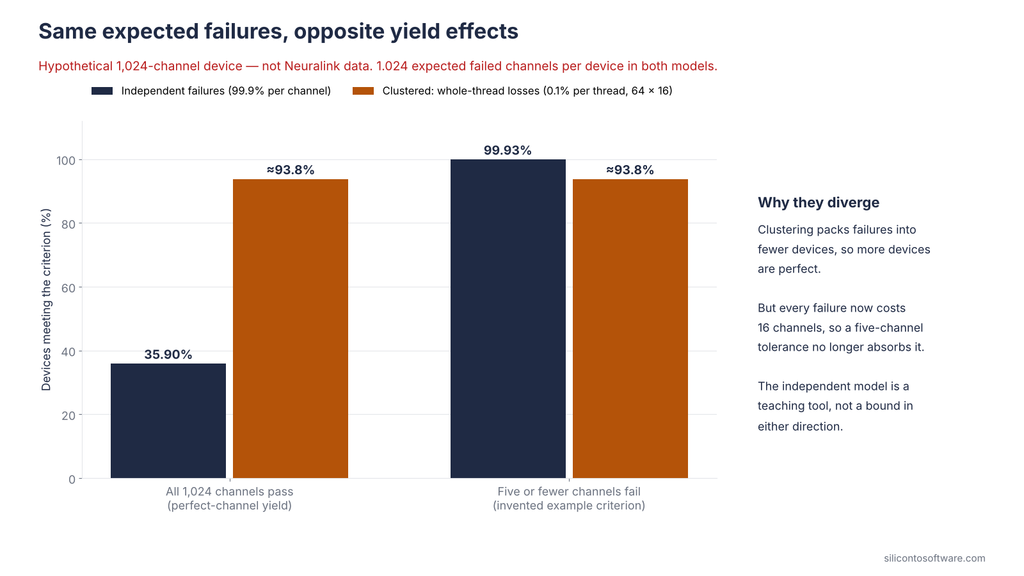
Consider an extreme hypothetical with the same expected number of failed channels per device, 1.024 in both models. Assume failures occur only as whole-thread losses. For illustration, assume exactly 16 channels on each of 64 threads. That distribution is a hypothetical assumption, not a verified N1 specification. Give each thread a 0.1% failure probability (64 × 0.001 × 16 = 1.024).
- Perfect-channel yield rises from 35.90% to about 93.8%, because failures concentrate into fewer devices.
- “Five or fewer failed channels” yield falls from 99.93% to about 93.8%, because any failure now costs 16 channels.
The expected defect count is the same, yet the two metrics move in opposite directions. The independent model is a teaching tool, not a bound in either direction. A real yield analysis needs the actual failure structure.
Manufacturing yield is not in-service reliability.
A device that ships with every channel passing can still lose channels in the body. In a May 8, 2024 update, Neuralink reported that in the weeks following its first participant’s surgery, a number of threads retracted from the brain, resulting in a net decrease in effective electrodes. It did not say how many. The cause was not publicly established, and no public evidence establishes a manufacturing defect as the cause.
The implant stayed in. Neuralink modified the recording algorithm to be more sensitive, improved how signals were translated into cursor movements, and enhanced the user interface, and later reported that the threads had stabilized and the implant’s performance had recovered.
Neuralink’s January 2026 update describes two separate next steps, each with its own stated purpose:
- Increasing from 1,000 to 3,000 electrodes to increase the volume of neural signal received.
- Exploring mechanical features to improve thread retention, to preserve that signal over time.
The retention work is aimed at the class of problem the first participant experienced. The electrode increase serves a different goal. Both are plans, not demonstrated devices. If the electrode increase proceeds, per-channel quality, failure structure, and acceptance definitions all become more consequential. More electrodes can also raise demands on front-end electronics, power, and telemetry, depending on architecture (engineering principle).
IDE, QMSR, and Change Control: The Rules That Set the Pace
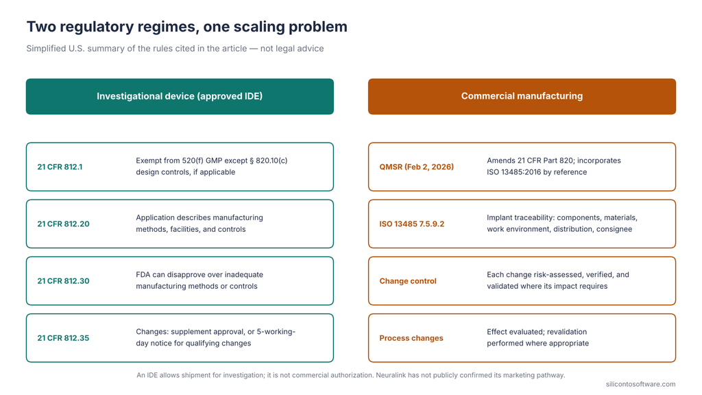
FDA’s Quality Management System Regulation took effect February 2, 2026, amending 21 CFR Part 820 and incorporating ISO 13485:2016 by reference.
Investigational devices are regulated differently, but they are not unregulated:
- Exemption. Under 21 CFR 812.1, an approved IDE exempts the device from section 520(f) good manufacturing practice requirements except § 820.10(c), if applicable, unless the sponsor states an intention to comply. FDA confirms that IDE devices are not exempt from design and development requirements under § 820.10(c) and ISO 13485 Clause 7.
- Application. The IDE application must describe the methods, facilities, and controls used to manufacture, process, pack, store, and install the device, in enough detail to judge its quality control.
- Review. FDA can disapprove an application over inadequacy of the methods, facilities, and controls used for manufacturing, processing, packaging, storage, and installation of the device.
- Changes during the trial. Some changes require FDA approval of a supplement. Others can proceed under a notice procedure, but only when the sponsor determines, on the basis of credible information, that they qualify as developmental changes in the device, including manufacturing changes, that do not constitute a significant change in design or basic principles of operation and that respond to information gathered during the investigation. For those, the sponsor must notify FDA within 5 working days of making them. The change’s significance determines which pathway applies.
For commercial implants, ISO 13485 Clause 7.5.9.2 sets specific traceability requirements. These include records identifying the components, materials, and work-environment conditions that could affect safety and performance, distribution records kept by distributors, and records identifying the shipping-package consignee. That record-keeping scales alongside the hardware.
Scaling doesn’t require freezing a design. It requires change control. Each change is assessed for risk, verified, and validated where its impact requires. Process changes are evaluated for their effect, with revalidation performed where appropriate.
During a trial, that engineering work sits alongside the IDE change-authorization rules above; it doesn’t replace them. Transdural insertion, thread-retention features, and a planned threefold electrode increase each move through that system. Iteration and validated volume can coexist, but they pull against each other.
Surgical Throughput Is a Separate System
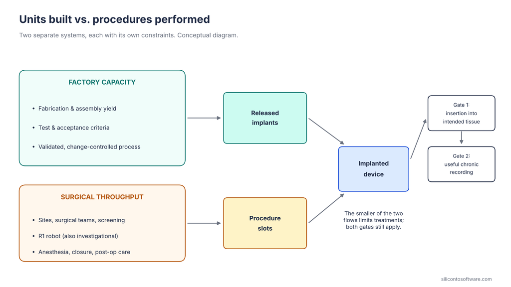
A finished implant becomes a treatment only through a procedure.
On June 30, 2026, Neuralink announced a procedure performed at Toronto Western Hospital in May 2026, according to the company. Neuralink reported that its robot inserted the electrode threads straight through the dura and into the cortex, keeping the dura intact. In plain terms, the dura was not surgically opened as in a conventional approach, though threads passing through it necessarily make small penetrations.
Neuralink’s April 2024 update had described its original procedure as including a craniectomy and durectomy before robotic thread insertion. Neuralink also reported that the participant controlled a cursor within an hour of surgery. Independently published procedural details remain limited.
Screening, anesthesia, cranial opening, closure, post-operative care, and site approvals all remain. “Almost entirely automated” hasn’t been broken down publicly.
The R1 robot is also being evaluated as part of the investigational system. Neuralink’s PRIME announcement says the study aims to evaluate the safety of both the N1 implant and the R1 surgical robot, and the trial registry lists the R1 Robot as a robotic electrode thread inserter alongside the implant.
A channel that passes factory acceptance still has two more gates to clear: insertion into the intended tissue location, and useful chronic recording. In its 2019 rodent work, Neuralink reported that auto-insertion reached up to six threads per minute, and that insertion success averaged 87.1% (SD 12.6%) across 19 surgeries. I could not verify comparable current-system insertion-rate or success-rate figures.
Units built and procedures performed are separate numbers, constrained by separate systems.
The Strongest Case Against This Analysis
The best counterargument deserves full weight. At relatively low trial-phase volumes, extensive inspection and screening can support production by rejecting nonconforming units, even without high process yield. Inspection cannot, on its own, demonstrate long-term implant reliability. Thin-film neural probes also build on decades of microfabrication work.
Neuralink describes its aim to maintain its “current record of zero serious device-related adverse events,” without defining the term or stating the period covered. On this view, the binding constraints are clinical and regulatory.
Parts of that are right. Low volume changes the yield economics, and a justified acceptance criterion transforms the arithmetic. It is incomplete in two places:
- Inspection can detect certain defects present before shipment, but not degradation that emerges in tissue.
- A design still changing at this pace limits how far existing validation and clinical data carry forward.
Milestones That Would Show Real Scale
If Neuralink mass production is under way, these are the disclosures that would show it:
- Enrollment totals and site counts from Neuralink or trial registries
- Primary-source disclosure of production capacity, output, or manufacturing partners
- Peer-reviewed, multi-year channel-stability data across participants
- Explant, revision, or replacement rates
- Published functional-channel definitions or acceptance criteria
- Step-level data on the automated surgical workflow
- A marketing submission to FDA, and any public inspection records
A Neuralink implant can work. The open question is whether Neuralink can demonstrate reproducible manufacturing, validated reliability, and clinically acceptable performance across many devices and patients, under acceptance criteria it can justify. Accelerated testing, qualification, and failure analysis can build much of that case quickly. The long-term human outcomes they are measured against still accumulate one implant-year at a time.
About the Author
Imran Valiani | Sales Director, PCB Electronics Manufacturing
20+ years working with major Bay Area and global tech clients. Founder of Silicon to Software, where I write about the hardware layer — PCB fab, AI gear, autonomous systems, and cyber — the stuff most tech writers have never touched. Literally.
Follow: X @SiToSoftware | LinkedIn
This article was developed with AI assistance and edited, fact-checked, and reviewed by the author. See my full AI disclosure.
Listen to the Silicon to Software podcast on Apple Podcasts, Spotify, or RSS.com — and watch on YouTube.
Sources
- Claire Wallace, MDDI Online — Elon Musk’s Neuralink to Ramp Up BCI Device Production in 2026. Informa Markets / MDDI, January 2, 2026. (Quotes Musk’s December 31, 2025 X post.)
- Texas Department of Licensing and Regulation — ATX1 – Third Floor Tenant Improvement (Project TABS2026011928). TDLR Architectural Barriers project record, registered February 6, 2026.
- Texas Department of Licensing and Regulation — ATX1 New Construction (Project TABS2024022676). TDLR Architectural Barriers project record, registered July 10, 2024.
- Austin Business Journal — Elon Musk’s Neuralink to expand Austin operations with $8.2M in renovations, new hires. Syndicated via Yahoo Finance, February 27, 2026.
- Neuralink — Two Years of Telepathy. Neuralink Updates, January 28, 2026. (Company statement.)
- ClearOne Inc. — Form S-1 Registration Statement. U.S. Securities and Exchange Commission (EDGAR), 2026. (Third-party filing; reports a Neuralink enrollment figure attributed to public statements.)
- Neuralink Corp — PRIME: An Early Feasibility Study of a Precise Robotically Implanted Brain-Computer Interface for the Control of External Devices (NCT06429735). ClinicalTrials.gov.
- Neuralink Corp — CAN-PRIME: An Early Feasibility Study of a Precise Robotically Implanted Brain-Computer Interface for the Control of External Devices (NCT06700304). ClinicalTrials.gov.
- Neuralink Corp — GB-PRIME: An Early Feasibility Study of a Precise Robotically Implanted Brain-Computer Interface for the Control of External Devices (NCT07127172). ClinicalTrials.gov.
- Neuralink Corp — UAE-PRIME: A Feasibility Study of a Precise Robotically Implanted Brain-Computer Interface for the Control of External Devices (NCT06992596). ClinicalTrials.gov.
- U.S. Food and Drug Administration — 21 CFR Part 812, “Investigational Device Exemptions” (§ 812.1, Scope). Electronic Code of Federal Regulations.
- U.S. Food and Drug Administration — 21 CFR § 812.20, “Application”. Electronic Code of Federal Regulations.
- U.S. Food and Drug Administration — 21 CFR § 812.30, “FDA action on applications”. Electronic Code of Federal Regulations.
- U.S. Food and Drug Administration — 21 CFR § 812.35, “Supplemental applications”. Electronic Code of Federal Regulations.
- Reuters — U.S. regulators rejected Elon Musk’s bid to test brain chips in humans, citing safety risks. Reuters Special Report, March 2, 2023. (Based on current and former Neuralink employees.)
- Neuralink — Technology. Neuralink, accessed October 16, 2026. (Company statement; enclosure, threads, and surgical robot descriptions.)
- Neuralink — PRIME Study Progress Update. Neuralink Updates, April 12, 2024. (Company statement.)
- Lex Fridman — Transcript for Elon Musk: Neuralink and the Future of Humanity | Lex Fridman Podcast #438 (DJ Seo; 02:11:42–02:13:26 and 03:08:52). Lex Fridman Podcast, August 2, 2024. (Human-generated transcript; the site notes it may contain errors.)
- Elon Musk; Neuralink — An Integrated Brain-Machine Interface Platform With Thousands of Channels. Journal of Medical Internet Research, 2019; 21(10): e16194. DOI: 10.2196/16194.
- IPC — IPC-6013F: Qualification and Performance Specification for Flexible/Rigid-Flexible Printed Boards. IPC (Global Electronics Association), 2026. ANSI Webstore listing.
- Seung-Hee Ahn, Joonsoo Jeong, Sung June Kim — Emerging Encapsulation Technologies for Long-Term Reliability of Microfabricated Implantable Devices. Micromachines, 2019. DOI: 10.3390/mi10080508.
- U.S. Patent 9,083,161 — Electrical feedthrough in a metal wall of a housing of an active medical device and method of making the same. USPTO. (Cited for the patent’s background description only.)
- Anne Vanhoestenberghe, Nick Donaldson — Corrosion of silicon integrated circuits and lifetime predictions in implantable electronic devices. Journal of Neural Engineering, 2013; 10(3): Article 031002.
- Cary A. Kuliasha, Jack W. Judy — in vitro Reactive-Accelerated-Aging (RAA) Assessment of Tissue-Engineered Electronic Nerve Interfaces (TEENI). 2018 40th Annual International Conference of the IEEE Engineering in Medicine and Biology Society (EMBC), 2018, pp. 5061–5064. DOI: 10.1109/EMBC.2018.8513458.
- Pavel Takmakov, Kiersten Ruda, K. Scott Phillips, Irada S. Isayeva, Victor Krauthamer, Cristin G. Welle — Rapid evaluation of the durability of cortical neural implants using accelerated aging with reactive oxygen species. Journal of Neural Engineering, 2015; 12(2): 026003. DOI: 10.1088/1741-2560/12/2/026003.
- Neuralink — PRIME Study Progress Update — User Experience. Neuralink Updates, May 8, 2024. (Company statement.)
- Quartz — Elon Musk’s Neuralink brain chip trial has already had some hiccups. Quartz, May 2024. (Cited only for the undisclosed number of retracted threads.)
- Neuralink — PRIME Study Progress Update — Second Participant. Neuralink Updates, 2024. (Company statement.)
- U.S. Food and Drug Administration — Quality Management System Regulation (QMSR). FDA, updated February 2, 2026.
- International Organization for Standardization — ISO 13485:2016 Medical devices — Quality management systems — Requirements for regulatory purposes. ISO, 2016. (Official catalog page; clause text not reproduced here.)
- Global Harmonization Task Force, Study Group 3 — Quality Management Systems – Process Validation Guidance (GHTF/SG3/N99-10:2004, Edition 2). GHTF, January 2004; hosted by IMDRF.
- Neuralink — Transdural procedure announcement. Neuralink official LinkedIn post, June 30, 2026. (Company statement.)
- Neuralink — Neuralink’s First-in-Human Clinical Trial is Open for Recruitment. Neuralink, 2023. (Company statement.)