Satellite PCB Engineering in 2026: How AI, Radiation-Hardened Electronics, and Advanced Circuit Boards Keep Satellites Alive
From SpaceX Starlink networks to NASA deep space missions, modern satellites rely on AI processors, radiation-hardened electronics, and ultra-reliable PCB engineering designed to survive the harshest environment ever faced by hardware.
Table of Contents
INDUSTRY PERSPECTIVE Twenty-plus years selling PCBs. Bay Area clients, space programs, defense contracts — I’ve had more spec calls than I can count. Here’s what I keep noticing: satellite PCB requirements have become the hardest, most misread topic in the whole field. This is my attempt to cut through it. Real docs. Real data. No fluff.
One bit. That’s it.
One high-energy particle flips one bit in a spacecraft’s memory, and a $300 million mission is done. No patch. No reboot. Nobody to call. I’ve been in this industry for over two decades, and that still hits me differently every time I think about it. What gets me is this — the whole answer to “how do you stop that?” lives inside the satellite PCB. That one board. Doing things no other piece of gear on Earth has ever had to do. And the people who design them? Most underrated engineers in the space race. I’ll stand by that forever.
Most folks think satellites just work. Like Wi-Fi — you don’t think about it; it’s just there. But under Starlink’s internet, NASA’s science missions, and the GPS that got you un-lost last week, satellite PCBs are running in conditions that would fry every device you own in hours.
Let’s go. Not from the start. From the thing that actually kills boards first.
Space Doesn’t Kill Chips with Cold. It Does It with Radiation.
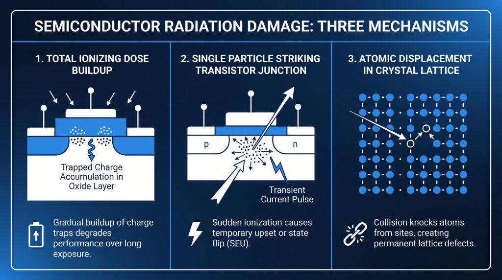
Everyone assumes cold kills the hardware. Wrong. Well — not wrong exactly, the heat swings are brutal, we’ll get there. But radiation is the real threat. Three ways it hits, and every satellite PCB designer has to fight all three at once:
Total Ionizing Dose (TID). Think of it as slow poisoning. Radiation builds up in the oxide layers and semiconductor structures over time, quietly degrading things until the device just stops working. Per ALLPCB’s radiation hardening guide, satellites typically need to survive 30 krad(Si) to over 100 krad(Si) of TID — exact numbers depend on orbit and how long the mission runs.
Single Event Effects (SEE). This one’s the scary one. One particle. One transistor junction. Bit flipped. Or worse — a latch-up that kills the whole component. Per HilPCB’s satellite PCB docs, you can’t fix this with one trick. You need Error-Correcting Code (ECC) memory, Triple Modular Redundancy (TMR) logic, and watchdog timer firmware all running together. One layer isn’t enough. Never is.
Displacement Damage. Particles knock atoms clean out of the crystal structure. Solar cells lose output. Sensors drift. It’s slow, quiet, and you can’t undo it.
I know what you’re thinking — what about the cold? LEO satellites swing from -65°C in shadow to +125°C in full sun, several times per orbit, every single day. Per ALLPCB’s combined-effects test docs, they often run boards through that full temp range while hitting them with 50 krad TID at the same time. Because that’s what orbit actually does to you. Both kill hardware. Radiation just sets the whole agenda.
SUPPLY CHAIN NOTE In my experience, the thing that blindsides programs isn’t the specs — it’s the lead times. Polyimide and ceramic-filled substrate materials have completely different supplier timelines, MOQ rules, and wait times than standard FR-4. I’ve watched good programs get caught off guard. Build it into your schedule from day one. Seriously.
The Chip That’s Flown More Miles Than Any Other Processor on Earth
Start here before you touch anything about Starlink or AMD or GPUs in orbit. Because if you don’t understand why this old chip exists, you won’t understand why the new stuff costs what it costs — or why you can’t just drop in a commercial part.
The BAE Systems RAD750 has been to Mars, Jupiter, and beyond. Curiosity rover. Juno. And per a JPL flight system paper in Space Science Reviews (Springer, February 2025), the main flight computer on Europa Clipper is the BAE RAD750 V3. It’s a hardened version of the old IBM/Motorola PowerPC 750 architecture.
Quick thing most articles mess up — the chip spec and the full board spec are not the same. Know which one you’re citing.
RAD750 CPU Chip
(per BAE Systems brochure)
| Specification | Value |
|---|---|
| Architecture | PowerPC 750 derivative (IBM/Motorola) |
| Fabrication | 0.25 µm CMOS · ~10.4M transistors |
| Clock Speed | 110–200 MHz |
| Performance | 240–300 MIPS |
| Power | ~5 Watts |
| TID Tolerance | 200–1,000 krad(Si) [200,000–1,000,000 rad(Si); 2,000–10,000 Gy] |
| Operating Temperature | -55°C to +125°C |
| SEU Rate (GEO) | 1 × 10⁻¹¹ upsets/bit/day |
Units note: this whole article uses krad(Si) — kilorads in silicon-equivalent absorbed dose. Standard US aerospace notation. 1 krad(Si) = 1,000 rad(Si) = 10 Gy. That Gy conversion is a one-time thing — everything else uses krad(Si).
Standard RAD750 SBC (CPU + Motherboard)
(per BAE Systems brochure)
| Specification | Value |
|---|---|
| Power | ~10 Watts |
| TID Tolerance | 100 krad(Si) [100,000 rad(Si); 1,000 Gy] |
| Operating Temperature | -55°C to +70°C |
Key Missions: Curiosity · Juno · Europa Clipper (V3)
ENGINEERING NOTE The chip and the full SBC board are two different things with two different ratings. Chip: up to 1,000,000 rads. Full SBC: 100,000 rads. Mix those up in a quote and you’ll have a bad day.
Your laptop clocks 3–4 GHz. A 2019 phone runs maybe 20x faster than this chip. And I think that’s where people completely miss the point — speed isn’t what this chip is for. It’s built to not die. Period. When you’re threading Jupiter’s magnetic field for ten years with zero chance of a service call, you don’t want fast. You want alive.
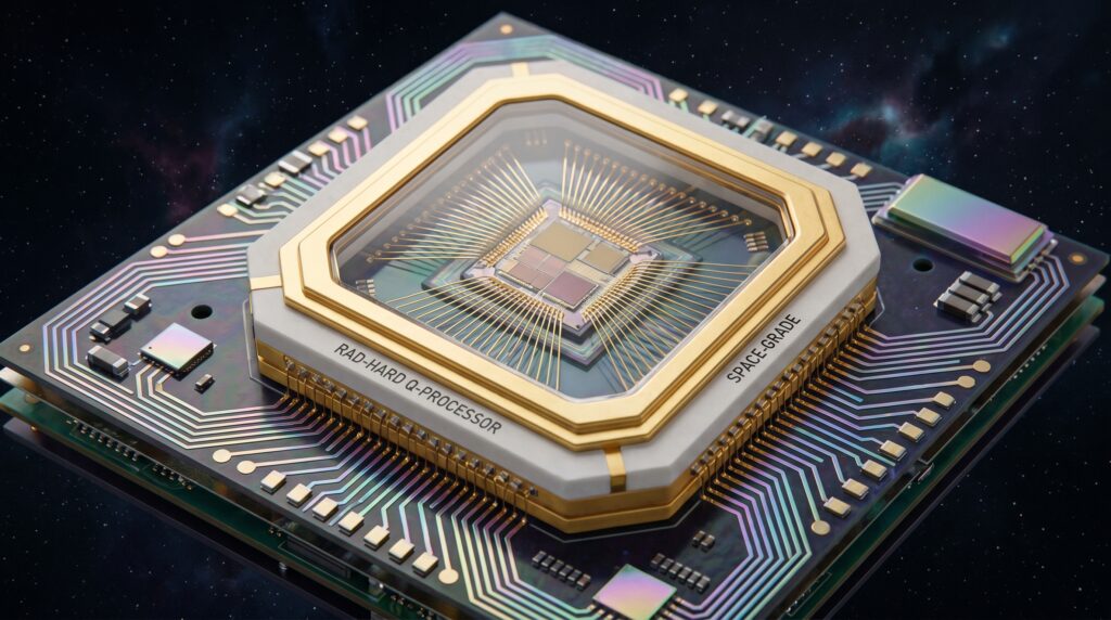
How does it stay alive? Redundant transistor pairs. Guard rings around every sensitive node. Silicon-on-insulator (SOI) fab that cuts transistors off from radiation-induced charge. And the PCB around it follows the same logic — tungsten and tantalum spot shields on the most exposed parts (copper layers give you EMI control and a bit of particle attenuation, but let’s be real, copper isn’t serious radiation shielding against heavy ions — the actual shielding mass comes from the housing and spot shields), conservative trace layout, full signal path redundancy.
To be honest? This stuff costs a lot. Per Electronics Media’s March 2026 report, rad-hard electronics run roughly 6–9% of total spacecraft subsystem costs. That’s why deep-space work has always been a government and big-contractor game. SpaceX cracked a different approach — not a new one; COTS plus system-level mitigation had been around for years — but they were the first to run it at the scale of thousands of satellites at once.
COTS + System-Level Radiation Mitigation: How SpaceX Changed the Economics
At the end of the day, it’s just math. You can’t afford rad-hard prices on every chip when you’re mass-producing a constellation. So the whole commercial LEO wave — Starlink leading the pack — switched to Commercial Off-The-Shelf (COTS) parts wrapped in system-level radiation mitigation.
Worth flagging something here that trips people up. Radiation-Hardened By Design (RHBD) is a chip thing. It’s choices made at the transistor level during IC design. It’s not a system-level label you can slap on a COTS setup.
What COTS actually uses is system-level mitigation. TMR voting logic. SEU scrubbing. Watchdog timer firmware. All wrapped around commercial chips that aren’t RHBD themselves. The AMD XQR Versal XQRVC1902 is different — it has RHBD baked in at the chip level, which is why it holds a MIL-PRF-38535 Class B ticket.
The core move is Triple Modular Redundancy (TMR). Three processors run the same job. A voting circuit picks the winner. One gets hit by a particle and spits out garbage? The other two outvote it. Per Space Micro Inc.’s TTMR patent docs (IEEE Aerospace Conference, 2006), TMR can get close to the SEU resilience of some rad-hard chips in low-radiation orbits — though it degrades as the radiation environment gets worse. Works great in LEO. Starts breaking down as you climb higher.
And LEO is exactly where it works because the radiation budget there is genuinely lighter than GEO or deep space. A 5-year LEO mission and a 15-year GEO mission are two completely different problems.
The chip on Starlink’s latest birds: AMD’s XQR Versal AI Core XQRVC1902 adaptive SoC. Per AMD’s press release on ir.amd.com (November 15, 2022), Class B qualification under MIL-PRF-38535. Done.
AMD XQR Versal AI Core XQRVC1902 — Verified Specifications
| Specification | Value |
|---|---|
| Processor Cores | Dual-core Arm Cortex-A72 + dual-core Arm Cortex-R5 |
| AI/ML Engines | 400 compute engines |
| INT8 Performance | 133 TOPS |
| DSP Engines | 1,968 |
| Logic Cells | ~900,000 |
| On-Chip Memory | 191 Mb |
| Fabrication | 7nm CMOS |
| Qualification | MIL-PRF-38535 Class B |
Per AMD’s Q3 2024 shareholder deck — backed up by PCMag and The Verge (October 30, 2024) — Lisa Su said it straight: SpaceX’s latest Starlink gen runs on Versal AI Core adaptive SoCs. Real AI capability on a satellite PCB in LEO. Right now.
One thing I’d flag if you’re spec’ing these for longer runs: AMD is chasing Class Y qualification for the XQRVC1902 in a new organic lidless package, per their blog (amd.com, November 2025). Class Y is the top tier under MIL-PRF-38535 — missions up to 15 years, GEO, lunar, deep-space. AMD’s roadmap says sampling in 2026, flight-qualified units in 2027. What’s shipping now is Class B. Not done yet. Worth tracking if you’re planning anything beyond five years in LEO.
(SpaceX keeps their PCB stack-up and layout details locked down. What we know: the chip. The board? Not public.)
What AI Is Actually Doing on Those Boards
“AI in space” is one of those phrases that’s been so overused it’s almost lost all meaning. I’ve noticed it in basically every press release since 2023. So let me be specific.
Per AMD’s qual press release and Signal Integrity Journal’s coverage of the XQR Versal AI Edge XQRVE2302 (March 2025), here’s what the hardware is actually built and sold for:
Beamforming. Real-time antenna steering. The AI engines handle dynamic processing instead of fixed routing tables.
Anomaly detection. Onboard inference catches out-of-norm behavior before it blows up into a failure — no waiting for a ground command cycle.
Cloud filtering. Why downlink terabytes of cloud cover? Filter it onboard and only send what matters. Bandwidth costs money.
Wildfire and vegetation work. Inference on satellite PCB-mounted AI engines at altitude. Starlink runs shells from roughly 340 km to 570 km, per a 2025 University of Arizona study on arxiv.org.
On the other hand, maybe I’m overselling the certainty here. AMD confirmed the hardware and the use case categories. SpaceX confirmed Versal is on Starlink. But the exact AI workloads actually running in production? SpaceX hasn’t said. Hardware is capable. Operational details are locked up.
Here’s the board-level point though. More AI compute means more heat. And in a vacuum — where there’s no convection cooling at all — every extra watt is a thermal problem. Not a heatsink problem. A laminate, thermal via, copper weight problem. Completely different engineering challenge.
What Actually Makes a Satellite PCB Different from a Commercial Board
I’ve been in PCB manufacturing for over twenty years. Here’s my honest take: people outside the industry consistently underestimate how different a satellite PCB actually is. It’s not a better commercial board. It’s a different product. Different rules, different materials, tested in ways that have no parallel in commercial work.
Substrate Material
FR-4? Out, for most missions. It breaks down under radiation and goes unstable in vacuum — outgassing and dielectric problems are the main killers (per PCBSync’s aerospace guide), with physical embrittlement showing up later at higher dose levels. FR-4 variants have flown on short LEO CubeSat runs where the mission is cheap and short enough that the tradeoff makes sense. But for anything serious? Not a chance.
On the other hand, maybe I’m being too hard on FR-4. Short missions, low orbits, tight budgets — there are legitimate cases. Just know what you’re signing up for.
For the real stuff, space-grade materials like cyanate ester and bismaleimide-triazine (BT) resins are rated for environments approaching 1 Mrad(Si), per HilPCB’s satellite PCB docs.
The go-to substrate is polyimide — specifically DuPont Kapton-based laminates. Been on space missions since Apollo, which still kind of blows my mind. Per PCBSync’s satellite PCB guide: runs from -200°C to +300°C, CTE around 12–14 ppm/°C, radiation resistance better than FR-4 across the board for both TID and displacement damage.
For RF and microwave payloads, PTFE-based laminates (polytetrafluoroethylene composites) are standard — low dielectric constant, minimal outgas, per ALLPCB.
Outgassing Compliance — NASA SP-R-0022A / ASTM E595
I’ve found this gets almost no coverage outside specialist circles. But it’s genuinely one of the first things a sharp aerospace buyer asks about. In vacuum, PCB materials off-gas. That contamination lands on your optics, your solar cells, your thermal surfaces. Per NASA’s SP-R-0022A spec and ASTM E595 testing:
| Parameter | Requirement |
|---|---|
| TML (Total Mass Loss) | < 1.0% |
| CVCM (Collected Volatile Condensable Material) | < 0.1% |
| WVR (Water Vapor Regain) | < 1.0% |
| Test Conditions | 125°C for 24 hours under controlled vacuum |
Pass, you fly. Fail, you redesign. That’s it.
Thermal Architecture — Not Thermal Management
No air in space. No convection. So the PCB stack itself is your thermal system — layer count, copper weight (3 oz/ft² to 6 oz/ft² in power areas per HilPCB), via density, part placement. All of it is thermal engineering as much as electrical engineering. Put a hot component in the wrong spot, and you get a hotspot that grinds down solder joints over thousands of heat cycles. Nobody knows until the board dies in orbit. Not recoverable.
In my experience, thermal architecture is one of the most important calls in the whole satellite PCB design. And it barely gets mentioned outside specialist papers.
Standards Baseline
Per PCBSync, AdvancedPCB, and NASA’s GSFC-STD-8001, space programs follow this stack. I’ll also tell you the two things I’ve seen trip up customers most often — they’re at the bottom.
IPC-6012 Class 3 — PCB fabrication baseline. The floor, not the ceiling.
IPC-6012 Space Addendum (DS) — What NASA Goddard actually mandates. More inspection, tighter thresholds, spacecraft-specific. Class 3 alone doesn’t get you there.
IPC-A-610 Class 3 — Workmanship acceptance.
J-STD-001FS — Soldering standard for space and military. (NASA-STD-8739.3 was canceled December 8, 2011 — programs switched to J-STD-001FS effective October 17, 2011, implemented today through NASA-STD-8739.6.)
NASA-STD-8739.6 — Workmanship implementation.
NASA-STD-8739.4 — Crimping.
ECSS-Q-ST-70-60C — Component derating for European programs.
The two things that confuse customers most: one, IPC Class 3 is the floor, not the full space qual stack — the DS addendum is what actually matters for flight hardware. Two, if your supplier quotes NASA-STD-8739.3 as their solder standard, push back hard. Canceled in 2011. Not acceptable.
Satellite PCB Qualification Testing
Per AdvancedPCB’s space-grade guide, here’s what a standard qual campaign looks like:
Thermal vacuum cycling (TVAC) to the full mission temperature range. Random and sine vibration to the launch vehicle spec. Shock testing. Radiation testing with cobalt-60 gamma sources to simulate TID buildup.
Not one test. Not two. All of them. Every board that reaches orbit has been through the whole thing.
The Real Tension: Rad-Hard vs. COTS Is Not Settled
I want to be straight about something. The industry loves to talk about this like it’s solved. It’s not.
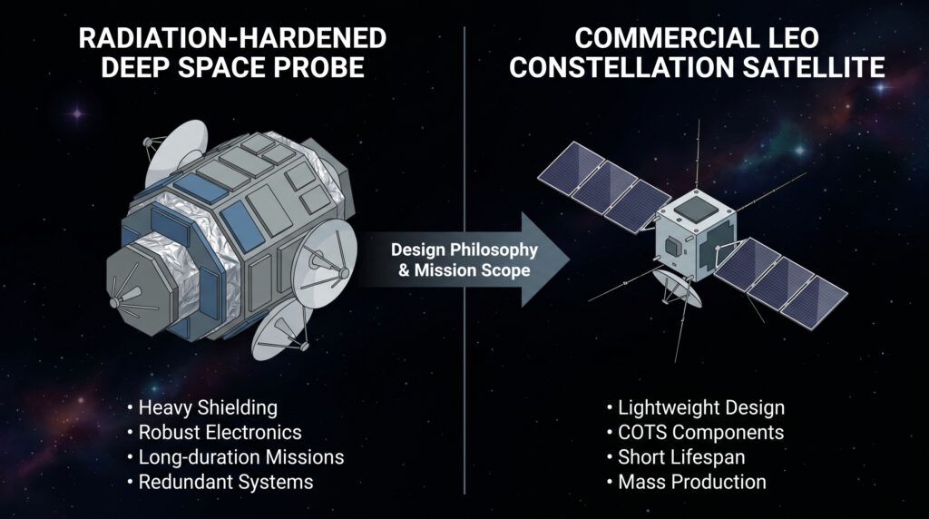
| Rad-Hard By Design | COTS + System-Level Mitigation | |
|---|---|---|
| Chip design | RHBD transistor/cell-level techniques | Standard commercial IC process |
| Cost | Very high (6–9% of subsystem cost) | Significantly lower at scale |
| Speed | Slow by design | Commercial performance |
| Failure tolerance | Near-zero margin | Accepts defined failure rate |
| Best for | Deep space, high-radiation orbits, long missions | Commercial LEO constellations |
COTS plus TMR works for big LEO fleets. Some failure rate is fine at scale. Per a 2025 University of Arizona study (arxiv.org), Starlink birds average 4–6 years lifespan and a 0.0128% daily failure probability. Across thousands of birds, that math holds.
But Europa Clipper? Flying through Jupiter’s magnetosphere — one of the worst radiation zones in the solar system — that math doesn’t fly. Zero tolerance. It runs the BAE RAD750 V3. Not COTS. Not TMR. The full rad-hard chip. Per the JPL paper in Space Science Reviews (Springer, 2025).
It’s genuinely a toss-up depending on orbit, mission length, and how much risk you’ll accept. Per Satellite Evolution Group’s May 2024 report, hybrid COTS architectures are trimming costs by 12–18% — but deep-space missions aren’t following that at all. The AMD XQR Versal is Class B qualified from LEO to GEO. Lines are shifting. Just not at the pace the marketing says.
I think both camps are right for their own use case. On the other hand, maybe I’m wrong to draw such a clean line — plenty of missions run both approaches on different subsystems at the same time. The tension is real, though. No clean answer.
What’s Coming — and What It Means for the Supply Chain
Direction is clear. Timeline? No one knows.
Rad-hard electronics market: roughly $2 billion in 2025, heading toward $3.4–3.8 billion by 2032, per Electronics Media’s March 2026 report. Satellite launches up 133% between 2020 and 2024 — about 1,200 per year to over 2,800. AI birds are pushing demand for rad-hard FPGAs at 300+ krad and hybrid COTS designs. And all of it still comes back to the same thing: satellite PCB engineering that can take what nothing else can.
November 2, 2025. Starcloud puts Starcloud-1 into LEO on a Falcon 9 — 60 kg, NVIDIA H100 GPU inside. Per CNBC (December 2025) and NVIDIA’s blog, first data center-class GPU ever in orbit. Starcloud says the H100 made it through launch and trained a language model on the complete works of Shakespeare up there. (That detail still gets me.)
Heat management: a system that dumps heat via thermal emission into space, built off ISS tech, per Awesome Agents’ Starcloud write-up (April 2026). (Side note — vacuum is not a heat sink. I see that phrase everywhere, and it’s wrong. Vacuum is an insulator. Heat in space moves by radiation from engineered surfaces, not by the vacuum doing anything. Just a pet peeve.)
Here’s what got buried in the coverage. The H100 is a commercial 4nm chip. Zero radiation hardening. No RHBD. No MIL-PRF-38535 of any class. NVIDIA’s own product docs show no rad-hard cert, no TID number, no SEU spec. That’s not a knock on Starcloud — it’s a deliberate call. Starcloud-1 sits at 325 km, expected mission life 11 months per Data Center Dynamics, then it burns up. Low altitude, short life, manageable TID. Smart tradeoff. Just don’t confuse it with a 15-year GEO design. Not the same thing at all.
China’s ADA Space and Zhejiang Lab launched 12 birds on May 14, 2025, on a Long March-2D out of Jiuquan — first batch of the Three-Body Computing Constellation. Per SpaceNews and China’s official gov news site (english.www.gov.cn), those 12 satellites put out a combined 5 POPS (peta ops per second), each running an 8-billion-parameter AI model, laser links between birds at up to 100 Gbps. Full plan is 2,800 satellites. Commercial, not state-run.
November 2025, Google Research dropped exploratory work on orbital AI infrastructure — Project Suncatcher — looking at TPU-equipped solar satellites in sun-synchronous orbit for AI compute, tied in with Planet Labs. Google calls it a moonshot. Their Trillium TPUs held up in particle accelerator tests simulating LEO. Meaningful result. Not the same as flight qual though. No hardware confirmed. No timeline locked. Worth watching. Not a program yet.
All roads lead back to the same question: how do you build a satellite PCB that keeps a GPU cluster cool in vacuum, survives -65°C to +125°C thermal cycling across the whole mission life — roughly 29,000 cycles over 5 years, 58,000 over 10 (that’s derived from orbital math, check it against ECSS-Q-ST-70-04 before you use it in a spec) — holds off TID for 5–10+ years, and never gets a single maintenance visit?
One last thing. The RAD750 won’t run things forever. NASA’s HPSC chip — built by Microchip Technology with SiFive RISC-V cores on a $50M NASA contract — passed functional testing at JPL in February 2026, targeting space qualification by late 2026. Per NASA’s LPSC 2025 presentation on ntrs.nasa.gov:
| HPSC Performance Metric | Value |
|---|---|
| Scalar Processing | ~100× RAD750 |
| Vector Processing | 256 GFLOPS |
| AI/ML (INT8) | 2 TOPS |
| Scalar equivalent | JPL put it roughly on par with a consumer CPU from the early 2020s for certain workloads |
TechTimes (May 2026) says early benchmarks hit 500× RAD750 on vector and AI workloads. The RAD750 age isn’t done. But the next thing is being tested right now.
The people who build these boards don’t trend. No keynotes. No viral moments. But every satellite that outlives its design spec — every beam that finds its target, every bit that holds — that’s a satellite PCB engineer’s work. Full stop.
About the Author
Imran Valiani | Sales Director, PCB Electronics Manufacturing — 20+ years working with major Bay Area and global tech clients. Founder of Silicon to Software, where I write about the hardware layer — PCB fab, AI gear, autonomous systems, and cyber — the stuff most tech writers have never touched. Literally. Follow: X @SiToSoftware | LinkedIn
This post was written with AI assistance. See my full AI disclosure.
Sources
Every technical claim in this article is sourced to a primary document, peer-reviewed publication, or manufacturer specification sheet. I’ve listed all 26 sources below because in a field this specialized — where a single conflated spec can send a design in the wrong direction — traceability matters. If you find a discrepancy between anything cited here and a more current primary source, I want to know. Use the Get In Touch page.
| # | Source | URL |
|---|---|---|
| 01 | ALLPCB — Radiation Hardening Techniques for Spacecraft Electronics PCB | allpcb.com/blog/pcb-knowledge/radiation-hardening-techniques-for-spacecraft-electronics-pcb-a-comprehensive-guide.html |
| 02 | HilPCB — Satellite PCB engineering documentation | hilpcb.com/en/blog/satellite-pcb/ |
| 03 | Wikipedia — RAD750 (CPU vs. SBC spec distinction) | en.wikipedia.org/wiki/RAD750 |
| 04 | petervis.com — RAD750 technical overview (BAE Systems) | petervis.com/Vintage%20Chips/PowerPC%20750/RAD750.html |
| 05 | Space Science Reviews, Springer (Feb 2025) — JPL Europa Clipper Flight System Overview | link.springer.com/article/10.1007/s11214-025-01139-9 |
| 06 | AMD ir.amd.com (Nov 15, 2022) — XQRVC1902 Class B / MIL-PRF-38535 press release | ir.amd.com/news-events/press-releases/detail/1101/amd-announces-completion-of-class-b-qualification-for-first-space-4gbqidfhggso |
| 07 | AMD Q3 2024 Shareholder Presentation — Versal in Starlink; corroborated by PCMag and The Verge (Oct 30, 2024) | ir.amd.com/news-events/press-releases/detail/1101/amd-announces-completion-of-class-b-qualification-for-first-space-grade-versal-adaptive-socs-enabling-on-board-ai-processing-in-space (primary) |
| 08 | Signal Integrity Journal (Mar 2025) — XQRVE2302 on-orbit AI applications | signalintegrityjournal.com/articles/3888-flight-qualified-amd-versal-xqr-socs-brings-accelerated-ai-inferencing-to-space |
| 09 | PCBSync — Satellite PCB requirements guide | pcbsync.com/satellite-pcb/ |
| 10 | PCBSync — Aerospace PCB guide | pcbsync.com/aerospace-pcb/ |
| 11 | AdvancedPCB — Space-grade PCB guide | advancedpcb.com/en-us/resources/blog/space-grade-pcbs-requirements,-materials,-standards,-and-design-priorities/ |
| 12 | University of Arizona / arxiv.org (2025) — Starlink constellation empirical survival analysis | arxiv.org/pdf/2603.25835 |
| 13 | Satellite Evolution Group (May 2024) — COTS/RHBD trends; 12–18% cost reduction | issuu.com/satelliteevolution/docs/seg-may2024-digital/s/47596995 |
| 14 | Electronics Media (Mar 2026) — Rad-hard market data; 6–9% subsystem cost | electronicsmedia.info/2026/03/06/radiation-hardened-electronic-components-market/ |
| 15 | CNBC (Dec 2025) — Starcloud-1 H100 in orbit | cnbc.com/2025/12/10/nvidia-backed-starcloud-trains-first-ai-model-in-space-orbital-data-centers.html |
| 16 | Data Center Dynamics — Starcloud-1; 325 km orbit; 11-month mission life | datacenterdynamics.com/en/news/starcloud-1-satellite-reaches-space-with-nvidia-h100-gpu-now-operating-in-orbit/ |
| 17 | NVIDIA H100 product documentation — absence of MIL-PRF-38535 qualification, TID tolerance rating, or SEU specification confirms no rad-hard certification exists | nvidia.com/content/dam/en-zz/Solutions/Data-Center/h100/h100-datasheet.pdf |
| 18 | NVIDIA Blog — Starcloud brings data centers to outer space | blogs.nvidia.com/blog/starcloud/ |
| 19 | Awesome Agents (Apr 2026) — Starcloud ISS thermal adaptation; $170M Series A | awesomeagents.ai/news/starcloud-170m-orbital-data-center/ |
| 20 | SpaceNews (May 14, 2025) — Three-Body Computing Constellation launch | spacenews.com/china-launches-first-of-2800-satellites-for-ai-space-computing-constellation/ |
| 21 | China Official Government News — Three-Body Constellation launch confirmation | english.www.gov.cn/news/202505/15/content_WS6825452ec6d0868f4e8f28e6.html |
| 22 | CGTN (May 2025) — Three-Body Constellation; 8B-param AI model; 100 Gbps ISL | news.cgtn.com/news/2025-05-14/China-launches-first-batch-of-space-computing-satellite-constellation-1DmXIysPKww/p.html |
| 23 | Google Research Blog (Nov 2025) — Project Suncatcher research initiative | research.google/blog/exploring-a-space-based-scalable-ai-infrastructure-system-design/ |
| 24 | NASA LPSC 2025 Technical Presentation — HPSC performance data | ntrs.nasa.gov/api/citations/20250002070/downloads/Powell-LPSC-2024-HPSC_for2025Mar12%2002252025_v2.pdf |
| 25 | TechTimes (May 2026) — HPSC 500× RAD750 benchmark; JPL functional testing | techtimes.com/articles/316745/20260517/nasas-new-radiation-hardened-chip-500x-computing-jwst-certification-late-2026-2028-moon.htm |
| 26 | SiFive press release (Sep 2022) — HPSC RISC-V contract announcement | sifive.com/press/nasa-selects-sifive-and-makes-risc-v-the-go-to-ecosystem |
| 27 | NASA GSFC-STD-8001 — Goddard PCB fabrication standard; mandates IPC-6012 Space Addendum (DS) | s3vi.ndc.nasa.gov/ssri-kb/static/resources/gsfc-std-8001.pdf |
| 28 | EPTAC — NASA adoption of J-STD-001FS; NASA-STD-8739.3 administratively cancelled December 8, 2011; programs adopted J-STD-001FS effective October 17, 2011 | eptac.com/blog/nasas-adoption-of-j-std-001-space-addendums |
| 29 | AMD blog (amd.com, Nov 2025) — Class Y qualification for XQRVC1902; 15-year mission support | amd.com/en/blogs/2025/amd-expands-space-grade-portfolio-enhances-in-orbit.html |
All claims cited to primary sources, peer-reviewed publications, or manufacturer documentation. SpaceX internal PCB stack-up specifications are proprietary and not publicly available — chip selection confirmed via AMD SEC filings. Starlink inter-satellite laser link speeds sourced from FCC filing summaries via trade press. Google Project Suncatcher is a stated research initiative per Google’s own language — not a confirmed commercial deployment. Market projections from Electronics Media are third-party analyst estimates. LEO thermal cycle figure is derived from orbital mechanics and should be verified against ECSS-Q-ST-70-04 before formal citation.